background image


3


1.


FEATURES


The 

DU 3500 AL automatic tuner

 has been primarily manufactured for an automatic PA, but it 

can also be used with any manual PAs as well. The tuner is primarily compatible with the OM 
POWER automatic PA. 

This tuner was designed for antennas calibrated to HAM BANDs. The maximum power can only 
be utilized with these antennas. With other antennas, it should be set at a lower power (max. 
2kW). 

The  major  advantage  of  the  tuner  is  that  during  competitions  it  is  possible  to  change  BANDs 
particularly quickly.  


2.


SPECIFICATIONS: 


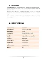
Frequency range :  

1,8-30MHz 

Matching range :  

max power  5:1  SWR 

Output Power :  

3,5kW 

Compatibility: 

All automatic  OM-POWER  

Tuning time: 

1-3 s  programmed memory 

Display :   

480x272  4,3” Color TFT Display 

Capacitor :  

510pF   5kV 

Ceramic switch :  

2 rotary switch 

Antenna switch :  

4 ant + 8 port 

DC power :  

12 - 13.8V  6A    

Dimensions (cm) :  

W34xD47xH16,5 

Weight :  

8 kg 

Summary of Contents for DU 3500 AL

Page 1: ...Made in Hungary USER MANUAL DU 3500 AL Automatic antenna tuner 3 5 kW ...

Page 2: ...or the external antenna switch 9 5 5 Antenna port 10 6 TUNING 11 7 Automatic mode 13 8 Manual setting 14 9 Example of connection Error Bookmark not defined 9 1 Example of connection for antennas Error Bookmark not defined 9 2 Example of connection for YAESU Error Bookmark not defined 9 3 Example of connection for Icom Error Bookmark not defined 9 4 Example of connection for USB micro KEYER II with...

Page 3: ...tennas With other antennas it should be set at a lower power max 2kW The major advantage of the tuner is that during competitions it is possible to change BANDs particularly quickly 2 SPECIFICATIONS Frequency range 1 8 30MHz Matching range max power 5 1 SWR Output Power 3 5kW Compatibility All automatic OM POWER Tuning time 1 3 s programmed memory Display 480x272 4 3 Color TFT Display Capacitor 51...

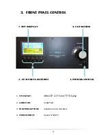
Page 4: ...PANEL CONTROL 1 TFT DISPLAY 480x272 4 3 Color TFT Display 2 CAPACITOR 510pF 5kV 3 FUNCTION BUTTONS Selection menu functions 4 POWER SWITCH Power ON OFF 1 TFT DISPLAY 2 CAPACITOR 3 FUNCTIONS BUTTONS 4 POWER SWITCH ...

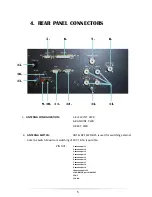
Page 5: ...ed for switching external Antenna Switch Maximum switching of 30V 0 5A is possible PIN OUT 1 antenna port 1 2 antenna port 2 3 antenna port 3 4 antenna port 4 5 antenna port 5 6 antenna port 6 7 antenna port 7 8 antenna port 8 9 antenna port 9 10 antenna port 10 11 COMMON port of ANT SW 12 NC 13 GND 5 6 7 8 9 10 11 12 13 14 15 16 17 ...

Page 6: ...uccessful operation If both CI V and TCVR cables are connected then CI V disables RS232 Otherwise selection of interface is done via TCVR type 12 PC DB 9 RS232 port is used for communication with your PC Please use setting you would normally use if using direct TCVR PC connection 13 GND 14 ANT OUTPUT 15 FUSE 6 3A 16 CI V Mono 3 5mm Jack for connection of ICOM TCVRs or devices that provide compatib...

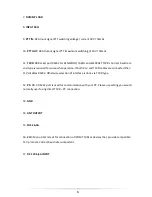
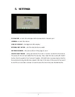
Page 7: ...ms used LOAD DEFAULT VALUES during manufacture the tuner is tuned to an ideal 50 ohm antenna The values for this can be recalled from the memory If we select this menu point with the SET button then the question Are You Sure appears If the SET button is pressed again then the base values set during manufacture reappear Warning In this case all the values set by you will be lost If one reconsiders ...

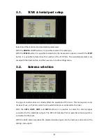
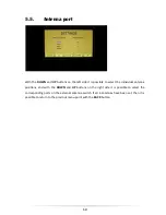
Page 8: ...tton and then we return to the settings menu 5 2 Antenna selection The type of antenna does not directly affect the operation of the tuner This menu point is only for ease of use so that it is easier to note which antenna is connected to the tuner With the ANT1 ANT2 ANT3 and ANT4 buttons it is possible to select the antenna types connected to the individual outputs The EXT SW indicates that an ext...

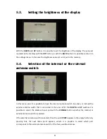
Page 9: ...na switch In this menu point it is possible to have the internal antenna switch be active or instead the external antenna switch that is connected to the tuner With the DOWN and UP switches it is possible to select the amateur band and with the CHANGE button whether the internal or external antenna switch is selected If the external antenna switch is selected then the word PORT appears in the empt...

Page 10: ...to select the individual antenna positions and with the DOWN and UP buttons on the right side it is possible to select the corresponding ports on the external antenna switch If all 4 antennas have been set then it is possible to return to the previous menu point with the BACK button ...

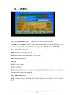
Page 11: ...nd the CAPACITOR The contents of the red window BAND the tuner s current band range QRA the frequency of the midpoint of the band range ANT the selected antenna Switches SW DN switch down SW UP switch up SAVE pressed briefly saves the values set pressed and held down exits the tuning menu in this case the values set are not saved ANT selects the antenna SEGM pressed briefly selects the band range ...

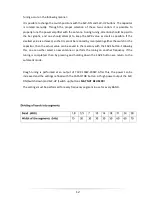
Page 12: ... be reduced by manipulating either the switch or the capacitor then the actual value can be saved in the memory with the SAVE button Following this one can either select a new antenna or perform the tuning on another frequency If the tuning is completed then by pressing and holding down the SAVE button we return to the automatic mode Rough tuning is performed at an output of TCVR 100W 200W After t...

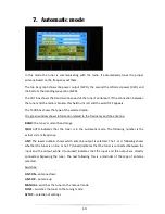
Page 13: ...ation related to the frequency and the antenna BAND the tuner s current band range QRA AUTO indicates that the tuner is in the automatic mode The following number is the actual current frequency ANT The lower number shows which antenna output is selected The T or U following shows whether the tuner is on line or not T tuned indicates that the tuner is connected between the input and the output whi...

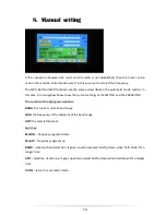
Page 14: ...ow boxes show the current settings of the SWITCH and the CAPACITOR The content of the light green window BAND the tuner s current band range QRA the frequency of the midpoint of the band range ANT the selected antenna Switches SEG DN frequency segment down SEG UP frequency segment up BAND amateur band selection It goes up when pressed briefly down when held down for a longer time ANT selection of ...

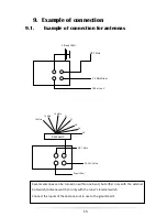
Page 15: ...ne band but either only with the external Ant switch Antenna switch or only with the tuner s internal switch Connect the inputs of the antennas not in use to the ground point 3 Band YAGI GP 7 MHz 3 5 MHz Dipol 160 m Inv V 2 1 3 4 14 MHz 14 MHz 14 MHz 21 21 28 28 28 GP 7 MHz YAGI 3 5 MHz Dipol 160 m Ant Switch ...

Page 16: ...16 ...

Page 17: ...17 ...

Page 18: ...18 ...

Reviews: