094278_t_de_gb_fr_es_it_pt_eseilwi_s
haacon hebetechnik gmbh – T49 (0) 9375 - 84-0 – Fax +49 (0) 9375 - 84-66
27
GB
Inserting the crank interrupts the power supply of the motor.
The appropriate switch has already been connected accor-
ding to the circuit diagram, if a factory control unit is installed.
Otherwise it is the responsibility of the operator to correctly
connect the switching element to the control unit.
The switch is a safety component.
– Examine regularly, however at least once annually, as well
as before commissioning.
The operator must ensure, that the brake is not inad-
vertently vented during normal operation.
e.g. the lever can be unscrewed with 400 V drive units
and screwed in into the crank mounting.
8.5 Drum Release
Drum release only without load!
Only for boat, vehicle salvage, and towing winches;
not permissible for lifting winches!
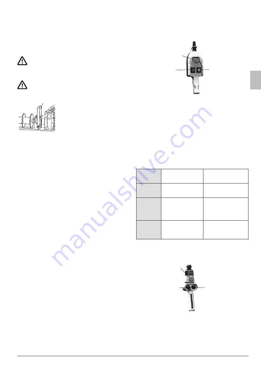
m
The drum can be separated from
drive unit and brake to remove the
unloaded rope.
z
Move coupling lever (m) toward
the drum.
The coupling is positive locking against independent release.
z
If necessary, turn the drum manually and release coupling.
The rope is not braked when taking off manually. Slack rope
can develop, causing the rope coil to jump of the drum. A pres-
sure roll (Chapter 8.2) can prevent this.
The coupling is equipped with a switch, which interrupts the
power supply of the motor. This switch has already been con-
nected according to the circuit diagram, if a factory control unit
is installed. Otherwise it is the responsibility of the operator to
correctly connect the switching element to the control unit.
The switch is a safety component.
– Check regularly, howeverat least once annually.
8.6 control with Pendant Pushbutton, direct
The control unit is attached to the gear, if not ordered other-
wise. The motor and a pendant pushbutton (standard supply
line 2 m) are connected to the control unit. The current is con-
ducted via the pendant pushbutton
directly
to the motor.
Emergency stop
Lowering /
unreeling the rope
Lifting /
reeling the rope
8.7 control with Pendant Pushbutton, indirect
The control unit is attached to the gear unit, if it has not
been ordered differently. The motor and, depending on
the equipment, all electrical switches (end position 8.1, slack
rope 8.3, emergency manual 8.4, coupling 8.5) are connected
to the control unit. The power supply to the motor is realised
indirectly
via control circuits.
Pendant pushbutton with control units similar to Chapter 8.6.
Circuit diagram –> Control box. The operator provides the
power supply (–> Chapter 5.1), examines the rotation direction
of the motor and the function of the switches. A warning lamp
(red) on the control box indicates a "malfunction" of normal
operation.
Possible causes:
Emergen-
cy stop
pressed
First release, then conti-
nue working.
Lamp extinguishes
Slack Rrpe
switch actu-
ated
Only „Lifting“ operation
is possible (reeling the
rope).
Lamp extinguishes, as
soon as the rope is tensi-
oned again.
Emergency
hand switch
actuated
Release emergency
hand switch.
As soon as the actuation
of the switch has been
released, the lamp extin-
guishes and continuing
work is possible.
coupling
switch actu-
ated
Engage coupling.
If the switch is no longer
actuated, the lamp extin-
guishes and continuing
work is possible.
The lamp does not light up in the case of disconnection in the
end positions (option 8.1). The device can be however only
driven in the opposite direction.
8.7.1 Operation via pendant push button
Emergency stop
Lowering /
unreeling the rope
Lifting /
reeling the rope


