background image

Functional and Operating Elements

12

7.2

Rear

11

13

12

15

14

25

26

!

A

27

28

29

11

Mains cable

12

Fuses

 (if this fuse is triggered,

see chap. 12.4)

13

Excess temperature setting dial

14

Air inlet opening

15

RS232C interface

25

Mains socket for temperature
control unit

26

Fuses for mains socket 25
(if triggered, see chap. 12.4)

27

Fuses for cooling circuit
(if triggered, see chap. 12.4)

28

Mains cable

29

Ventilation grid

Artisan Technology Group - Quality Instrumentation ... Guaranteed | (888) 88-SOURCE | www.artisantg.com

Summary of Contents for Cryostat DC5-K75

Page 1: ...cess underutilized and idle equipment along with credit for buybacks and trade ins Custom engineering so your equipment works exactly as you specify Critical and expedited services Leasing Rentals Demos In stock Ready to ship TAR certified secure asset solutions Expert team I Trust guarantee I 100 satisfaction All trademarks brand names and brands appearing herein are the property of their respect...

Page 2: ...e Versailles D 76227 Karlsruhe Paramus NJ 07652 91160 Champlan Tel 49 0 18050HAAKE oder 49 0 721 4094 444 Tel 201 265 7865 Tel 33 1 64 54 0101 Fax 49 0 721 4094 418 Fax 201 265 1977 Fax 33 1 64 54 0187 E mail helpdesk haake de http www haake usa com http www rheo fr Artisan Technology Group Quality Instrumentation Guaranteed 888 88 SOURCE www artisantg com ...

Page 3: ...on 10 7 Functional and Operating Elements 11 7 1 Front 11 7 2 Rear 12 8 Assembly if necessary after servicing 13 9 Connecting Hoses 14 9 1 Plastic hoses 14 9 2 HAAKE metal hoses 15 9 3 Pressure pump 16 9 3 1 Temperature controlling an object in the internal bath 16 9 3 2 Connection of external closed systems 16 10 Filling with Bath Liquid 17 10 1 Recommended bath liquids 17 10 2 Filling with heat ...

Page 4: ...5 3 Pump or motor overloading 31 15 4 Sensor breakage or short circuit 32 15 5 Undefined fault 32 15 6 Range exceeded 32 15 7 Parity fault 32 15 8 External fault 32 15 9 Fault eliminated 32 16 Testing the Safety Features 33 16 1 Excess temperature protection 33 16 2 Low liquid level protection 33 17 RS232C Interface for DC5 34 17 1 Connecting the DC5 to a computer 34 17 2 Interface parameters 35 1...

Page 5: ...the next operating step to be carried out and what happens as a result thereof 1 2 Symbols used on the unit Caution Read the instruction manual Adjustment possibility for setting the cut off point for excess temperature protection Menu selection Value alteration higher lower Enter key Reset button for usage after a fault or interruption Artisan Technology Group Quality Instrumentation Guaranteed 8...

Page 6: ...ortant characteristics already during manufacturing and record the results for future reference The Final Test label on the product is a sign that this unit has fulfilled all requirements at the time of final manufactur ing Please inform us if despite our precautionary measures you should find any product defects You can thus help us to avoid such faults in future 3 Your Contacts at HAAKE Please g...

Page 7: ... for every unit operator Only use this unit solely for the intended application Repairs alterations or modifications must only be car ried out by specialist personnel Considerable damage can be caused by improper repairs The HAAKE service department is at your disposal for repair work Do not operate the unit with wet or oily hands Do not expose the unit to spray water or immerse it in water Do not...

Page 8: ...e protection against electric shocks by grounding all parts which carry the risk of electric contact The device must only be connected to mains recep tacles with a protective ground Protection IP 20 according to EN 60529 i e regarding the protection against accidently touch ing live parts and damage by foreign matter it has been ensured that foreign bodies with a thickness or diame ter of more tha...

Page 9: ...inst one single fault This one fault will effectively occur automatically if you do not read this manual do not correctly set the excess temperature protection i e your safety reserves have already been used up Such faults can include e g Fault in the temperature control unit Excess temperature poss fire danger Leakage in the liquid circuit or Evaporation of heat transfer liquid Low liquid level p...

Page 10: ...it to a stable safe condition the heat transfer liquid in the heating unit gradually ad justs to ambient temperature but For units with switched on compressor cooling this cooling remains functional and thus cools the heat transfer liquid to the lowest reachable temperature 5 3 Applications The circulator is intended for temperature controlling samples within the circulator s own bath or for tempe...

Page 11: ...N 61000 4 4 quick transient interference variable ENV 50141 high frequency asymmetrical amplitude modulated EN 61000 4 8 magnetic field with power engineered frequency There are thus no limitations placed on usage A declaration of conformity can be supplied with the ordered unit on request Our strict standards regarding minimum operating quality and the resulting considerable amount of time and mo...

Page 12: ...i e upright lubrication oil can leak from the compressor into the cooling circuit If the refrigerated circulator is started up whilst still in this state the compressor may be damaged to the lack of oil Therefore Rest the unit for 24 hours after setting up 6 5 Ventilation Keep all ventilation grids 23 and 29 free from obstruc tion to ensure unhindered air circulation Blocked ventilation grids lead...

Page 13: ...on also Start key 3 Menu selection key 4 Heating control lamp 5 Menu position display 6 Set or actual temperature display fault display 7 Value alteration higher lower 8 Enter key 21 Cooling unit mains switch 22 Drainage nozzle 23 Ventilation grid removeable four mounting points 24 Handles Artisan Technology Group Quality Instrumentation Guaranteed 888 88 SOURCE www artisantg com ...

Page 14: ...s temperature setting dial 14 Air inlet opening 15 RS232C interface 25 Mains socket for temperature control unit 26 Fuses for mains socket 25 if triggered see chap 12 4 27 Fuses for cooling circuit if triggered see chap 12 4 28 Mains cable 29 Ventilation grid Artisan Technology Group Quality Instrumentation Guaranteed 888 88 SOURCE www artisantg com ...

Page 15: ...ads or stopper 4 Insert the screws 31 through the plate and screw tight Mounting the swivel part of the circulation set 40 5 Preparation Unscrew the screw 9 from the unit shaft and loosen screw 9a of the circulation set 40 6 Locate swivel part 40 7 Insert screw 9 Slightly tighten both screws 9 and 9a Mounting the plate onto the cooling unit K75 8 Locate the plate 37 with the attached temperature c...

Page 16: ... wider hose diameter and the vessel to be temperature controlled should be placed as close as possible to the circu lator High operating temperatures will lead to high tem peratures on the hose surface this is even more so at the metal nozzles In this case DO NOT TOUCH The required hose material is dependent on the heat transfer liquid used Hoses must not be folded or bent A wide radius should be ...

Page 17: ... high degree of safety and are suitable for both low and high temperatures The metal hoses are attached directly to the nozzle A gas kets are not required The hoses must not be extremely bent or subjected to mechanical strain These hoses are available in lengths of 0 5 1 0 and 1 5 me ters from HAAKE Couplings for connecting two hoses are also available if other lengths should be required for a par...

Page 18: ...temperature jacket or coil or a heat exchanger Hose connection From the pressure port at the rear to the external ob ject and then back to the return port at the front If it c annot be avoided that the external object is si tuated higher than the circulator the heat transfer will only not flow back on the condition that the system is completely tight and leak free To be on the safe side it may be ...

Page 19: ...er 10 1 Recommended bath liquids 5 to 95 C Distilled Water Normal tap water leads to calcareous deposits neces sitating frequent unit decalcification Calcium tends to deposit itself on the heating ele ment The heating capacity is reduced and service life shortened Water of course can be employed up to 95 C howev er above 80 C water vaporization reaches a level which necessitates the liquid to be c...

Page 20: ...nsuitable bath liquids are liquids which e g are very highly viscous much higher than 30 mPa s at the respective working temperature have corrosive characteristics or tend to cracking It is absolutely mandatory that the overtemperature cut off point is set lower than the flash point for the heat transfer liquid selected See chapter 16 The highest working temperature as defined by the EN 61010 IEC ...

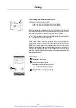
Page 21: ...Quite often closed external systems cannot be prefilled as suggested In this case the internal bath of the unit has to be filled to the max level After starting the unit the pump will feed the necessary liquid to the external system Should the demand be higher than the volume difference between high and low the low liquid level sensor will be activated and the pump switched off In this case 1 Repl...

Page 22: ... prevent the liquid from running out right away 3 Pull out plug pin in one quick motion The liquid will start to run out 4 Possible residues can be drained by tilting the circula tor slightly Hot heat transfer liquid should not be drained When certain conditions make draining necessary please act safety conscious Wear protective clothing and protective gloves Artisan Technology Group Quality Instr...

Page 23: ... is live as soon as this connection has been made whether the refrigerated bath has been switched on at the mains switch or not 12 2 Checking the liquid circuit Before switching on check again to make sure that the pres sure and suction ports are either connected with each other or blocked with covering plugs or alternatively if an external object is to be temperature controlled that the hoses are...

Page 24: ...ng is visible a certain cooling down time should be allowed approx 5 min before the dip switch can be pressed again Do not use tools do not use force Both destroy the fuse If the fuse should be triggered again after resetting the unit probably has a defect In this case the unit should be sent in for servicing Artisan Technology Group Quality Instrumentation Guaranteed 888 88 SOURCE www artisantg c...

Page 25: ...second compressor of the K75 is always switched on automatically after a delay of 30 seconds for protection When the unit is started under unfavourable envi ronmental conditions the pressostat safety device may respond after about 1 minute If this happens please press the reset button 2 Usually the unit will then start correctly without going into fault sta tus again However if fault status appear...

Page 26: ...ease the value shown on the display 6 via the keys 7 If you keep one of the keys 7 depressed the first de gree of temperature alteration is shown slowly in tenths of a degree After this the temperature alteration rate accelerates to five times quicker 3 Press the Enter key 8 The selected value is confirmed as the new set value The new value is not saved until the Enter key has been pressed The cir...

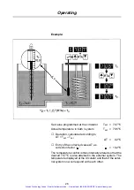
Page 27: ...g de vice calibrated or gauged thermometer It is entered into the circulator as the correction factor RTA system and remains stored there The resolution of the correction factor according to the RTA system is 0 01 C Possible change 2 5 C Entry see example overleaf 1 Press the key 3 until is shown on the small dis play 5 2 Alter the value shown on the display 6 using the keys 7 or 3 Press the Enter...

Page 28: ...ntry of the corrected value T as correction factor 0 2 C The temperature control is thus internally altered so that the desired 70 7 C is also attained in the external system The temperature displayed at the circulator and that of the exter nal system now correspond with each other Artisan Technology Group Quality Instrumentation Guaranteed 888 88 SOURCE www artisantg com ...

Page 29: ...y 5 2 Alter the value shown on the display 6 using the keys 7 or Setting is possible with a resolution of 1 C and only with positive values 3 Press the Enter key 8 The selected value is confirmed as new limit value The new value is not saved until the Enter key has been pressed The circulator continues to use the old value The display 6 automatically switches back to actual temper ature display af...

Page 30: ...eezes under cer tain unfavorable external conditions e g mains voltage surges or electro magnetic disturbances In this state it no longer reacts to further entries and displays a random value as the set value e g 90 C which cannot be altered The unit can be rendered operable again by a simpleRESET as follows 1 Switch the unit off at the mains switch 2 Keep the keys and simultaneously depressed whi...

Page 31: ...angers caused by an uncon trolled heating up of the heat transfer liquid above the de sired set temperature The cut off temperature is adjusted with the excess temper ature setting dial 13 Proper protection can only be guaranteed if the cut off point has been correctly set There are two main aims for correct setting Safety primary importance Protection against ignition of the heat transfer liquid ...

Page 32: ...emperature turn the excess temperature dial 13 backwards very slowly to the left until the unit cuts off acoustic signal fault shown at display 6 3 Then set the set temperature to the actual temperature 35 C 4 Reset the unit via the Reset key 2 after the heat transfer liquid has cooled down somewhat The unit can now be used for temperatures below 35 C As soon as 35 C is reached it is securely swit...

Page 33: ...ue slightly according to specifi cations made in chapter 14 1 1 the control function is defective Return unit for servicing 15 2 Low liquid level The low liquid level protection can be triggered if there is not enough liquid in the bath check for leaks top up if necessary fluid has evaporated top up if necessary 15 3 Pump or motor overloading The motor or pump is blocked It can take 10 min or long...

Page 34: ...tions detailed in chapter 13 10 Return the unit for repairs in case of repeated faults 15 7 Parity fault All data is saved together with a corresponding parity bit in the permanent storage SRAM When this data is accessed the respective parity bit is checked In case of a parity fault the fault display S Err is shown on the display The heating then shuts itself down Switch the unit off and start it ...

Page 35: ... see chapter 14 1 that is lower than the desired set temperature Switch on the circulator and check if the circulator really does switch itself off at the set cut off temperature If not follow the specifications detailed in chapter 14 1 1 It may be deemed necessary to have the unit checked over by qualified service personnel 16 2 Low liquid level protection Drain the heat transfer liquid slowly du...

Page 36: ...ecting the DC5 to a computer The pin assignment required when connecting a DC5 to a computer via a 9 pin RS232C socket is as follows 3 2 7 8 5 RxD Received Data TxD Transmitted Data CTS Clear to Send RTS Request to Send Signal ground DTR DC5 3 2 7 8 5 6 6 Cable 9 pin to 9 pin 9 pin RS232C 3 2 7 8 5 6 TxD RxD RTS CTS DSR Computer 9 pin RS232C 3 2 7 8 5 6 The pin assignment required when connecting ...

Page 37: ... parameters can only be set altered via the DC5 op erating panel Handshake OFF without RTS CTS ON with RTS CTS Parität OFF without parity odd odd parity E even parity Baud rate 600 1200 2400 4800 9600 These three transfer parameters cannot be altered via the in terface DC5 maximum baud rate We recommend a maximum Baud rate of 4800 bps The communication between the PC and the DC5 circulator should ...

Page 38: ...perature to the last value entered via the DC5 keyboard itself and not the value given by the computer 17 5 Correction value If the correction value is set via the computer two hori zontal lines are shown on the display 5 The correction value only remains saved for as long as the supply volt age is switched on Additionally a If the RS232C connection is interrupted the circula tor controls the temp...

Page 39: ... C e g set 20 0 C S 02000 set 10 5 C S 1050 VZ replaces 1 charac RTA Factor c c cr call up Offset value VZ XX XX C cr lf e g 01 20 C c 1 2 C c VZ value cr set Offset in 1 100 C automatic switching to REMOTE op eration as well as blocking the ENTER key VZ value 0000 0255 0 C 2 55 C Space and are possible as positive sign e g c 1 23 C c 0123 or c 0123 Start and stand by operation ST cr STOP control ...

Page 40: ...as blocking the En ter key Lock U cr Switching from REMOTE operation as well as releasing the Enter key Unlock 17 8 Operating status B cr call up operating status x x x x x x x x cr lf 0 sensor OK 1 sensor defective 0 no alarm EXTERNAL 1 alarm EXTERNAL 0 no alarm pump 1 alarm pump 0 no alarm low liquid level 1 alarm low liquid level 0 no alarm excess temperature 1 alarm excess temperature 0 main r...

Page 41: ...PEN COM2 4800 N 8 1 CS0 DS0 CD0 AS 1 loop b INPUT command b if b X then markend if b x then markend repeat command PRINT 1 b PRINT PRINT return message PRINT GOSUB enter GOTO loop markend END enter A read loop X ASC INPUT 1 1 IF X 10 THEN read end A A CHR X GOTO read loop read end print a RETURN Note Only capital letters are accepted for commands Artisan Technology Group Quality Instrumentation Gu...

Page 42: ...urfaces causing corrosion If corrosion e g small rust marks should occur in spite of this cleaning with stainless steel caustic agents has proved to be suitable These substances should be applied accord ing to the manufacturers recommendations 18 1 Cleaning the fins of the liquefier In order to maintain the cooling capacity of the unit cleaning has to be done two to four times per year depending o...

Page 43: ...30x100 Bath depth T mm 200 Bath volume max l 6 Dimensions WxT mm 380x460 Unit height H mm 720 Weight kg 65 Permissible ambient temp C 10 40 Total wattage max VA 3450 Order no for 230 V 50 60 Hz 400 5751 19 1 Fuse values Unit type Mains voltage Fuse s at the rear panel Fuse s in the unit DC5 230V 2x6 A 1xT40 mA 115V 1x15 A 1xT63 mA 100V 1x12 A 1xT63 mA K75 230V 50Hz 2x6 A 2x10 A 1xT630 mA 200V 50 6...

Page 44: ...ss This could lead to burn out of the com pressor motor windings The second compressor of the K75 is always switched on automatically after a delay of 30 seconds This delay is for protection of the compressor When the unit is started under unfavourable envi ronmental conditions the pressostat safety device may respond after about 1 minute If this happens please press the reset button 2 Usually the...

Page 45: ...device if cooling is actually required The compressor starts with a slight jerk 20 2 Starting up again after a power failure The temperature control module switches itself off in case of a power failure Display 6 flashes over all segments Switching on again is only possible after the reset key 2 has been pressed This is due to safety reasons The unit reacts in the same way if is switched on via a ...

Page 46: ...ease the value shown on the display 6 via the keys 7 If you keep one of the keys 7 depressed the first de gree of temperature alteration is shown slowly in tenths of a degree After this the temperature alteration rate accelerates to five times quicker 3 Press the Enter key 8 The selected value is confirmed as the new set value The new value is not saved until the Enter key has been pressed The cir...

Page 47: ...g de vice calibrated or gauged thermometer It is entered into the circulator as the correction factor RTA system and remains stored there The resolution of the correction factor according to the RTA system is 0 01 C Possible change 2 5 C Entry see example overleaf 1 Press the key 3 until is shown on the small dis play 5 2 Alter the value shown on the display 6 using the keys 7 or 3 Press the Enter...

Page 48: ...ntry of the corrected value T as correction factor 0 2 C The temperature control is thus internally altered so that the desired 70 7 C is also attained in the external system The temperature displayed at the circulator and that of the exter nal system now correspond with each other Artisan Technology Group Quality Instrumentation Guaranteed 888 88 SOURCE www artisantg com ...

Page 49: ...y 5 2 Alter the value shown on the display 6 using the keys 7 or Setting is possible with a resolution of 1 C and only with positive values 3 Press the Enter key 8 The selected value is confirmed as new limit value The new value is not saved until the Enter key has been pressed The circulator continues to use the old value The display 6 automatically switches back to actual temper ature display af...

Page 50: ...eezes under cer tain unfavorable external conditions e g mains voltage surges or electro magnetic disturbances In this state it no longer reacts to further entries and displays a random value as the set value e g 90 C which cannot be altered The unit can be rendered operable again by a simpleRESET as follows 1 Switch the unit off at the mains switch 2 Keep the keys and simultaneously depressed whi...

Page 51: ...quipment Have surplus equipment taking up shelf space We ll give it a new home Learn more Visit us at artisantg com for more info on price quotes drivers technical specifications manuals and documentation Artisan Scientific Corporation dba Artisan Technology Group is not an affiliate representative or authorized distributor for any manufacturer listed herein We re here to make your life easier How...

Reviews: