background image

2

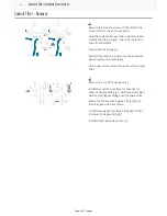
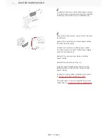
Align the upper bracket [1] with the upper three

holes drilled in the enclosure panel using the

template.

Raise the left side window and install the coolant

chiller upper bracket [1] onto the enclosure panel

using the sealing washers [2] and machine screws

[3]

Note:

For VM-2, VF-2YT and VF-2SSYT

equipped with SMTC-50 and built before 01/

2020. These machines have a stiffener [4] on the

back panel that requires a spacer. Install the

spacers [5] (P/N 59-1822) in between the back

panel and the upper bracket. Install the longer

screws (P/N 40-1978) and washers (P/N 45-0184).

Do not fully tighten the machine screws. Make

sure the position of the upper bracket can still be

adjusted by hand.

3

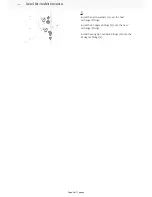
Use the hooks on the top of the coolant chiller to

hang the coolant chiller from the upper bracket.

4

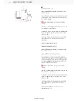
Install the hex nuts [1] onto the upper bracket.

Do not fully tighten the hex nuts.

Align the coolant chiller with the lower two holes

drilled in the enclosure panel using the template.

Raise the left side window and install sealing

washers [2] and machine screws [3] onto the

coolant chiller.

Note:

For the VF-2YT that have a stiffener on

the back panel install the spacers (P/N 59-1822) in

between the back panel and the coolant chiller.

Use the longer screws (P/N 40-1978) and washers

(P/N 45-0184).

Tighten all the fasteners securing the upper

bracket and coolant chiller.

Coolant Chiller Installation Instructions

Page 5 of 11 pages

Summary of Contents for Coolant Chiller AD0468

Page 1: ...will show you how to install the Coolant Chiller option on a VF machine Machine Compatibility Next Generation Control 100 19 000 1000 Software Version For instructions on how to operate the coolant chiller refer to COOLANT CHILLER OPERATION Coolant Chiller Installation Instructions Page 1 of 11 pages ...

Page 2: ...to prevent coolant leaks Disconnect all the coolant hoses from the coolant filter 2 Remove the 1 2 NPT hose barb 1 Install the 1 2 NPT hose barb 1 onto the 1 2 brass 90 degree fitting 2 Install the assembled barb and 90 degree fitting onto the check valve Rotate the 3 4 brass 90 degree fitting 3 such that the open side faces down Install the wing tip hose barb fitting 4 onto the 3 4 brass 90 degre...

Page 3: ...Coolant Chiller Installation Coolant Chiller Installation Instructions Page 3 of 11 pages ...

Page 4: ... VF Secure the drill template to the enclosure in the location specified by the diagram Height Y 60 152 cm Place the the drill template on the left 3 side of the stiffener 2 for these models VF 3YT 50 VF 5 50XT VF 5 50TR VF 5 50 For all other models place the drill template on the right 4 side of the stiffener 2 Use a 5 16 inch drill bit to drill holes through the enclosure in the locations marked...

Page 5: ... Make sure the position of the upper bracket can still be adjusted by hand 3 Use the hooks on the top of the coolant chiller to hang the coolant chiller from the upper bracket 4 Install the hex nuts 1 onto the upper bracket Do not fully tighten the hex nuts Align the coolant chiller with the lower two holes drilled in the enclosure panel using the template Raise the left side window and install se...

Page 6: ...over the heat exchanger fittings Install the 90 degree fittings 2 onto the heat exchanger fittings Install the wing tip hose barb fittings 3 onto the 90 degree fittings 2 Coolant Chiller Installation Instructions Page 6 of 11 pages ...

Page 7: ...s not kink Route the coolant hose 1 from coolant pump to the filter assembly Route the coolant hose 2 from the filter assembly to the heat exchanger Route the coolant hose 3 from the waycover washdown to the filter assembly though the cable carriers under the coolant chiller Secure the waycover washdown hose with a cable clamp 5 Route the temperature sensor cable 4 along the waycover washdown hose...

Page 8: ...Electrical Installation Coolant Chiller Installation Instructions Page 8 of 11 pages ...

Page 9: ...1 Power down the machine and set the main circuit breaker to OFF Coolant Chiller Installation Instructions Page 9 of 11 pages ...

Page 10: ...rge VF shown Remove the enclosure panel 1 located below the control cabinet Remove the coolant connector box Route the temperature sensor cable 2 and coolant chiller power cable 3 through the back of the coolant connector box and then through the base casting and up though the hole in the bottom of the control cabinet Note Follow the existing coolant cables routing Use the provided magnet and cabl...

Page 11: ...ables from the cabcool coolant chiller power supply onto the terminal block Reinstall the removed red white and black power cables Reinstall the sheet metal cover 1 Plug the coolant chiller power cable into the labeled outlet on the cabcool coolant chiller power supply Install the coolant chiller software patch Refer to PATCH FILE LOAD UNINSTALL NGC For instructions on how to operate the coolant c...

Reviews: