STEP 2
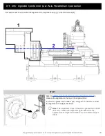
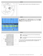
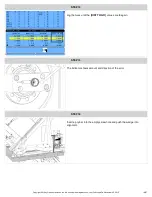
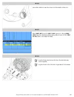
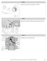
Look at the indicator to see the amount and the direction of the error.
STEP 3
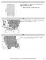
Press
[ZERO RET]
to set the
[DIST TO GO]
values to 0. Press
[HAND
JOG]
to see the coordinate position display. We will return to this 0
[DIST
TO GO]
position in the steps that follow.
STEP 4
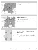
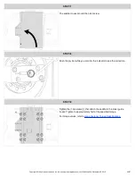
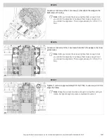
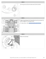
Jog the Z Axis a small amount to move the indicator away
from the spindle.
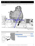
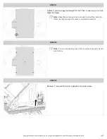
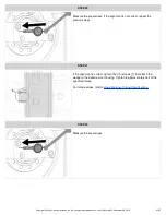
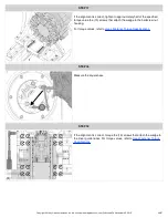
You will jog the X and Y Axes to move the turret to get access
to the screws.
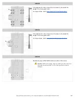
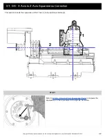
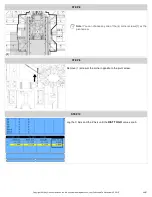
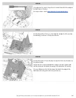
There are (16) screws [1] that attach the saddle to the linear guide trucks
(4 for each truck), and (10) screws [2] that attach the saddle to the
ballscrew nut housing.
Copyright 2018 by Haas Automation, Inc. No unauthorized reproduction | Last Published On November 05, 2015
15/67

