GB
14
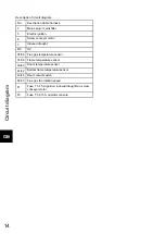
Description Circuit diagram:
No.:
Description Cable harness
3
Mains plug / mains filter
5
Electric ignition
6
Screw conveyor motor
7
Induced draught
8/9
OC
35/36
Flue gas temperature sensor
37/38
Flame temperature sensor
39/40
Room temperature sensor
41/42
Bottom flame temperature sensor
43/44
Door contact switch
48-50
Flue gas fan rotation speed
F1
Fuse T 3,15 A ignition, induced draught fan, screw
conveyor motor
F3
Fuse T 0,315 A operator console
Summary of Contents for 0553508020000
Page 4: ......
Page 6: ...Dimensions GB 2 2 Dimensions ...
Page 10: ...Maintenance work GB 6 Figure 1 Removing the flue baffle ...
Page 17: ...Circuit diagram GB 13 6 Circuit diagram Circuit diagram IO 33 3 ...
Page 19: ......


