background image

  13

between the relevant switch on and switch off 
times.  

¾

  After the completion of the day of the week 

programming, the programming window for this 
day of the week can be saved and quitted by 
pressing the left key (Back). 

¾

 The other days of the week must be 

programmed in the same way.  

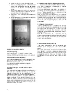
7.3.3.4  Example of programming for “Monday” 

¾

  Press the left key repeatedly until the Info 

screen appears. 

¾

  Then press the middle bottom key. 

¾

  Now the screen in which the days of the week 

can be selected appears. 

¾

  Move the cursor with the two middle keys so 

that the MO field (MO – means Monday) is 
highlighted with the cursor. 

¾

  Then press the right key (Edit). 

¾

  Now the programming window for “Monday” 

appears 

¾

  The first column contains position numbers 1, 2 

and 3 

¾

  In the second column, the switch on times 

(marked by the letter E) are programmed in 15 
minute jumps with the two middle keys. 

o

  You can move from the left column to 

the right with the right key (arrow). 

¾

  In the third column, the switch off times (marked 

by the letter A) are programmed in 15 minute 
jumps with the two middle keys. 

¾

  In the fourth column, the desired target room 

temperature is assigned to the period that falls 
between the relevant switch on and off times. 

¾

  After completion of the programming of the day 

of the week, the programming window for this 
day of the week can be saved and quitted by 
pressing the left key (Back). 


8. Cleaning and maintenance work 

 The functioning of your device depends to a large 
extent on regular expert maintenance. Because of the 
ash accumulation resulting from the combustion of wood 
pellets, constantly recurring cleaning and maintenance 
work needs to be carried out. This will permit operation 
to be as trouble-free as possible. 
The frequency of maintenance in turn depends to a large 
extent on the pellet quality (ash content). Quality pellets 
have a low ash content of about 0.2-0.3%. However, if 
the ash content is higher (0.5% and over), the interval 
from maintenance to maintenance is reduced and the 
accumulation of ash increases by 2 or 3 times. This 
results in lower heat output and an increased fan 
rotation speed.  


We therefore recommend checking and/or 
cleaning the flue gas passes after 1,000 kg of 
pellets at the latest. (See Figure 8 a+d). 
 

L

 Attention!  

Devices that are not maintained in accordance with 
our specifications must not be operated. Failure to 
observe this point will invalidate all guarantee 
claims. 
 

As soon as you detect ash and clinker deposits in the 
cold combustion pot, it must be cleaned. (

See Figures 5 

+6). 

If this is not done, the clinker will continue to 

accumulate. Then the device will no longer be able to 
ignite properly. Pellets can pile up in the combustion pot. 
In extreme cases, this can reach all the way back to the 
pellet chute. Backfire in the pellet container and 
smouldering in the pellet tank might possibly result. 

This will destroy your device and is not covered in 
your guarantee


L

 Attention!


Before cleaning work starts, the stove must be 
cooled down, the On/Off toggle switch must be in 
the “0” position and the mains cable must be 
disconnected! 
Once the cleaning work is completed, the correct 
operating status of the device must be re-
established: Put the combustion pot in correctly, 
close the combustion chamber door. 


8.1 Cleaning the surface 

Dirt on the upper surface of the stove may be cleaned 
off with a damp cloth or if necessary with mild soapy 
water. You are advised against using corrosive cleaning 
agents and solvents since these might damage the 
surfaces. 
 

8.2 Cleaning the glass panel 

 
To clean the viewing panel, you must first open the 
stove door. Dirt on the glass panel can be removed with 
a glass cleaner or with a damp sponge on which you 
have sprinkled some of the wood ash present. 
(Environmentally friendly). 
Cleaning the glass panel may only be done with a 
cooled down stove in the OFF operating mode. 
 

8.3 Cleaning the combustion pot 

During operation, deposits may form in the combustion 
pot. How quickly the combustion pot becomes dirty 
depends solely on fuel quality. The deposits or 
encrustations must be removed from time to time. 


Summary of Contents for 417.08

Page 1: ...ion pot it must be cleaned See operating instructions If this is not done there will be more and more clinker Then the device will no longer be able to ignite properly Pellets may pile up in the combustion pot In extreme cases this can reach all the way back to the pellet chute Backfire in the pellet container and smouldering in the pellet tank might possibly result This will destroy your device a...

Page 2: ...oom temperature in Heating operating mode 12 7 3 3 Auto operating mode weekly programme 12 7 3 3 1 Setting date and time 12 7 3 3 2 Auto operating mode weekly programme 12 7 3 3 3 Setting the target room temperature in Auto operating mode weekly programme 12 7 3 3 4 Example of programming for Monday 13 8 Cleaning and maintenance work 13 8 1 Cleaning the surface 13 8 2 Cleaning the glass panel 13 8...

Page 3: ... time The heating of the air in the room and the creation of comfortable living conditions is mainly achieved by convection This allows you to quickly warm up even cold rooms that have been unheated for a lengthy period The cooler air of the room enters the stove at the bottom of the cladding is heated and flows out again at the top in the area of the slats The proportion of radiant heat is given ...

Page 4: ...children s and guests attention In particular any cleaning staff should be informed and instructed regarding the possible unexpected heating up of the stove Placing non heat resistant objects on or near the heating device even when it is cold since it can ignite again by itself is forbidden Do not lay any laundry on the stove to dry Clotheshorses for drying clothes and the like must be positioned ...

Page 5: ...es are also suitable Since excess pressure may build up at the smoke outlet because of the way that the pellet stove works with an induced draught fan all fume outlet pipes as far as the intake to the fireplace must be gas tight It is also essential to ensure that the flue tube does not stick out into the open cross section of the chimney The use of wall lagging is recommended for the insertion in...

Page 6: ...target temperature by 1ºC and the stove has cooled down to a temperature of below 80C 5 1 Ignition phase In the Ignition phase the grate is filled with a precisely defined quantity of fuel and this quantity of fuel is ignited with a glow igniter The Ignition phase which is divided into 10 zones is ended after reaching a precisely defined temperature on the flame temperature sensor and the control ...

Page 7: ...s to Standby operating status 5 5 Standby There is no combustion process going on in this operating status all the components the induced draught fan and the screw conveyor are stopped the ignition is switched off and the device is in a waiting position Before the stove can switch back from Standby operating status to the Ignition phase operating status two ignition conditions must be fulfilled 1 ...

Page 8: ...the Heating mode operating status the stove cools down below a minimum temperature a safety shutdown is initiated and the following error message is shown on the display Shutdown flue gas temperature heating mode too low The stove cannot restart its heating mode until the error message has been cleared on the operator console and the desired operating mode has been reset 6 Description of operator ...

Page 9: ...n selection arrow Right Enter the selected menu item 6 2 3 Setting the operating mode Back Select Heating Auto Operating mode Off Functions of the keys Left Display Info screen 1 Middle top Selection up Middle bottom Selection down Right Save the selected operating status 6 2 4 Setting the time and date Back Select 15 00 24 01 2005 Information Time Date Functions of the keys Left Display Info scre...

Page 10: ... 5 Description Key lock child safe 1 Menu Room target actual 0 28 C 15 00 We 23 01 2004 Information Operating mode Auto Operating status Standby In Info screen 1 you can activate a key lock Activating the key lock Hold the Menu key down for about 10 seconds until Key lock activated appears on the display Deactivating the key lock Hold the Menu key down for about 10 seconds until Key lock activated...

Page 11: ...than the current room temperature Before commissioning remove any stickers and any accessories from the ash pan and the combustion chamber This also applies to any transportation handling securing materials Check that the combustion chamber cladding is attached to its fastenings This might have slipped out of its position as a result of the transportation or installation of the stove Check that th...

Page 12: ...y on the operator console repeatedly until the information screen appears In the Info screen press the right key Menu Now the main menu appears In the main menu place the cursor on Date Time with the two middle keys Press the right key Select Now the programming window for the date and time appears In the programming window press right key Edit Now programming is activated select the field to be e...

Page 13: ...nance to maintenance is reduced and the accumulation of ash increases by 2 or 3 times This results in lower heat output and an increased fan rotation speed We therefore recommend checking and or cleaning the flue gas passes after 1 000 kg of pellets at the latest See Figure 8 a d LAttention Devices that are not maintained in accordance with our specifications must not be operated Failure to observ...

Page 14: ... mode Procedure Press the left key on the operator console repeatedly until the Info screen appears then press the right key Menu with the two middle keys move the cursor to Operating Modes press the right key Select with the two middle keys move the cursor to OFF press the right key Save the stove begins to cool down Once the stove has completely cooled down cleaning work can begin Attention The ...

Page 15: ... 8b Removing the side wall Undo the screws and remove both the covers of the openings Now you can clean the exposed insides of the flue gas passes See Figure 8 c d After completion of the cleaning make sure that when putting back the covers the seals are seated in the right positions It is essential to replace defective seals Figure 8c Cleaning covers Figure 8d Cleaning covers open 8 7 Cleaning th...

Page 16: ...t and this initiates the cooling down phase Figure 10 Screw conveyor motor 1 Screw conveyor motor 2 Condenser 3 Thermosensor flue gas 4 Induced draught fan 5 Overheat cutout 6 Master switch 7 Mains socket 8 Heat exchanger 9 Outside air connection 9 3 Combustion pot with tray The combustion pot is made of high grade stainless steel The special design of the combustion pot guarantees clean and extre...

Page 17: ... Control unit 3 Fuses T 3 15A 4 Fuse T 0 315A 5 Backup battery 6 Condenser screw conveyor motor 9 6 Operator console The operator console is built into the pellet tank in such a way that the display with its four function keys is easily accessible All the parameters necessary for the operation of the stove can be set with this operator console Access to these parameters is divided into two levels ...

Page 18: ...its the stove to be shut down safety shutdown 9 8 Flame or combustion chamber temperature sensor combustion chamber thermosensor The flame temperature is measured in Heating mode operating mode The flame temperature measured is an indicator of the energy level in the grate and hence the basis of the air volume required for the combustion of the energy level located in the grate Here the ACTUAL fla...

Page 19: ...n pot 7 Combustion tray 8 Pellet chute 9 Door contact switch 9 13 Flue tube connection The diameter of the flue elbow is 80 mm The flue tube must be connected to the fireplace in accordance with official regulations For questions in connection with this please contact your local chimneysweep Because of the way the pellet stove works with a combustion air fan high pressure is generated at the flue ...

Page 20: ...7 kg Duration of burn with one charge min max about 10 hrs 30 hrs about 10 hrs 30 hrs about 10 hrs 30 hrs Permitted fuel Low dust wood pellets to Ö Norm Eco standard M 7135 DIN 51731 EN 14961 2 Diameter 6 mm Length max 30 mm Diameter 6 mm Length max 30 mm Diameter 6 mm Length max 30 mm Room heating capacity to Ö Norm M 7521 max 230 m3 max 230 m3 max 230 m3 Room heating cap y to DIN 18893 constant ...

Page 21: ...21 Figure 20 Dimensions of Pelletto 432 08 Figure 21 Dimensions of Pallazza 517 08 ...

Page 22: ...neer 3 Shutoff materials correction 3 Check burner Cause The automatic fuel reduction has initiated a safety shutdown Correction Contact the service engineer 4 Shutoff flue gas temp Heating mode 5 Cause Flue gas temperature is starting to fall rapidly despite maximum heat output for a long period The following circumstances might lead to this No pellets present The screw conveyor is not rotating i...

Page 23: ...flue temp in Heating mode too high 22 Cause The highest permitted flue gas temperature was exceeded The following circumstances might lead to this Too much fuel is being supplied to the burner Flue gas temperature sensor defective Correction Contact the service engineer 7 Shutoff combustion chamber door open 6 or 9 Cause The door is open for longer than 1 minute during operation The damper at the ...

Page 24: ...onsole and restart the device 17 Bottom flame temp sensor 2 interruption 24 Cause Bottom flame temperature sensor defective or not connected Correction Contact the service engineer 18 Safety shutdown tolerance variation flame temperature 26 Cause Burner dirty pellets have low calorific value Correction Clean burner if necessary change pellet type 19 Bottom flame temperature TFL max exceeded 27 Cau...

Page 25: ... of the central unit is empty Backup battery not connected Correction Check connection Replace backup battery Contact the service engineer 23 LED board not connected 51 Cause The connection between the LED board and the central unit is interrupted The following circumstances might lead to this Connection cable is not connected to the LED board or to the central unit or is defective Correction Chec...

Page 26: ...efective connection cable between operator console and control unit Check plugs and sockets otherwise call in the service engineer Fire burns with a tall yellow flame wood pellets piling up in the combustion pot and or the viewing panel is excessively sooty 1 The combustion air supply to the combustion pot is blocked by ash deposits Turn off the stove and let it cool down Remove the combustion pot...

Page 27: ...S SOHN OFENTECHNIK GMBH Urstein Nord 67 A 5412 Puch Pellet Kaminofen Typenbezeichnung Fault Cause Correction 4 Screw conveyor jamming 1 Pull out the mains plug and move the screw conveyor motor back and forth otherwise 2 empty pellet container and clean screw conveyor channel with vacuum cleaner otherwise 3 call in the service engineer 5 Flue gas fan defective Call in the service engineer Pellet s...

Page 28: ...135 EN14961 2 HAAS SOHN OFENTECHNIK GMBH Urstein Nord 67 A 5412 Puch Pellet Kaminofen Typenbezeichnung Nennwärmeleistung Zugelassener Brennstoff Bauart EN 14785 Registrier Nr RRF 85 10 2533 Prüfstellenkennziffer 1625 CO NWL CO Teillast Staub bez auf 13 O2 5 mg Nm3 0 007 0 01 Wirkungsgrad 90 40 97 20 Mindestabstände zu brennbaren Bauteilen seitlich 10 cm hinten 10 cm vorne im Strahlungsbereich 80 c...

Page 29: ...29 Figures 22 Replacement parts 417 08 432 08 Figures 23 Replacement parts 517 08 ...

Page 30: ...0561008007401 0561008007401 0561008007401 0561008007401 Draught baffle plate 21 0561008005701 0561008005701 0561008005701 0561008005701 Allen key 6 mm 9001700060005 9001700060005 9001700060005 9001700060005 Stand 22 0561008006941 0561008006941 0561008006941 0561008006941 Mains cable 0089500380005 0089500380005 0089500380005 0089500380005 Device plug with master switch 23 0089500110005 008950011000...

Page 31: ...31 14 Circuit diagram ...

Page 32: ... 9 OC 35 36 Flue gas temperature sensor 37 38 Flame temperature sensor 39 40 Room temperature sensor 41 42 Bottom flame temperature sensor 43 44 Door contact switch 48 50 Flue gas fan rotation speed F1 Fuse T 3 15A ignition induced draught fan screw conveyor motor F2 Fuse T 3 15A reserve F3 Fuse T 0 315A operator console ...

Page 33: ...raught incorrectly carried out repair work or other in particular subsequent changes to the heating appliance or flue gas pipework stove pipe and chimney use of unsuitable fuels incorrect operation overloading the devices see the manufacturer s operating instructions wear on the parts made of iron or fire clay directly exposed to the flames in so far as they are not covered by the guarantee 1a inc...

Page 34: ...auxiliary ranges for wood coal and oil Fireplace inserts for wood Accessories for stoves and fireplaces Accessories for central oil supply Air humidifiers HAAS SOHN Sales in Germany OFENTECHNIK GMBH HAAS SOHN Ofentechnik GmbH Urstein Nord 67 Herborner Straße 7 9 A 5412 Puch D 35764 Sinn Tel 0043 0 662 44955 0 Telephone 0049 0 2772 5010 0 Fax 0043 0 662 44955 210 Fax 0049 0 2772 5010 99 Email offic...

Reviews: