


17
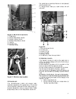
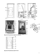
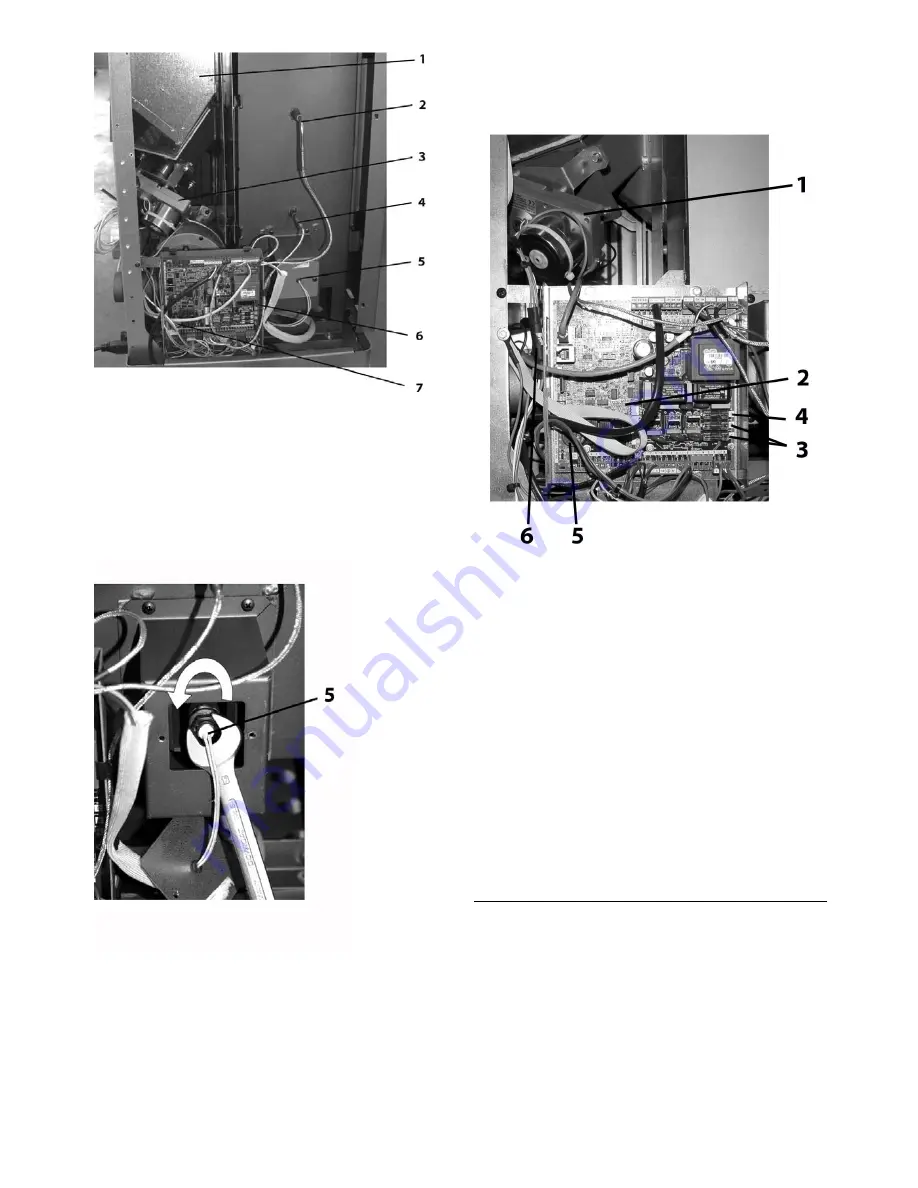
Figure 12: Electrical components
1 = Pellet tank
2 = Flame temperature sensor
3 = Screw conveyor motor
4 = Bottom temperature sensor
5 = Ignition
6 = Control unit
7 = Backup battery
Figure 13: Stainless steel ignition
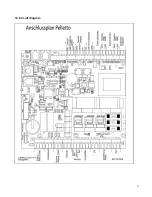
9.5 Control unit
The microprocessor control unit ensures safe,
automatic operation of the pellet stove. The control
unit controls the interaction of the components e.g.
induced draught fan, screw conveyor motor, flame
temperature sensor, room temperature sensor etc..
The pellet stove’s electrical fuses are incorporated
into the control unit.
To change these fuses you must remove the left
side wall.
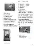
Figure 14:
1. Screw conveyor motor
2. Control unit
3. Fuses T 3,15A
4. Fuse T 0,315A
5. Backup battery
6. Condenser, screw conveyor motor
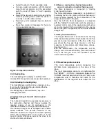
9.6 Operator console
The operator console is built into the pellet tank in
such a way that the display with its four function keys
is easily accessible.
All the parameters necessary for the operation of the
stove can be set with this operator console.
Access to these parameters is divided into two levels.
The first level is intended for the stove operator.
The second level is intended for customer service and
may only be accessed by inputting a special access
code.
Description of the first level – the one for the operator:
The operator can make the following adjustments with
or read the following information on the display of the
operator console:
•
Start or stop the device
•
Set the desired target room temperature (in
“Heating” operating mode).


