


24
12.
Flame temp. sensor interruption (23)
Cause:
•
Flame temperature sensor defective or
not connected
Correction:
¾
Contact the service engineer
13.
Flame temp. sensor short circuit (24)
Cause:
Flame temperature sensor defective
Correction:
¾
Contact the service engineer
14.
Induced draught fan cannot reach
target rotation speed (15)
Cause:
The induced draught fan is not
running at the correct rotation
speed
The following circumstances might lead to this:
¾
Induced draught fan defective
¾
Connection cable from the rotation speed
sensor (Hallsensor) is broken or poor
contact in the connector on this
connection cable
¾
Electricity supply to the fan motor
interrupted
Correction:
¾
Contact the service engineer
15.
No connection to the boiler board –
Check cable (17)
Cause:
•
The connection between the central unit
and the operator console is interrupted.
The following circumstances might lead to this:
•
Connection cable is not connected to the
operator console or to the central unit
•
Connection cable is damaged
Correction:
¾
Check that the connection cable is
connected to both units, the operator
console and the central unit.
¾
Contact the service engineer
16.
Shutdown after power cut (18)
Cause:
•
A safety shutdown was triggered after a
power cut
Correction:
¾
Clear the fault on the operator console
and restart the device
17.
Bottom flame temp. sensor 2
interruption ( 24 )
Cause:
•
Bottom flame temperature sensor
defective or not connected
Correction:
¾
Contact the service engineer
18.
Safety shutdown tolerance variation,
flame temperature ( 26 )
Cause:
•
Burner dirty, pellets have low calorific
value.
Correction:
¾
Clean burner, if necessary change pellet
type
19.
Bottom flame temperature T
FL
max.
exceeded ( 27 )
Cause:
•
Burner
dirty
Correction:
¾
Clean
burner
20.
“Clean combustion chamber” function
instruction
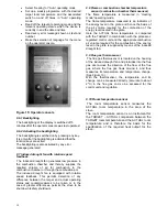
The display on the operator console starts flashing.
(The backlighting switches on and off and the
“Clean combustion chamber” instruction appears).
The instruction to clean the combustion chamber
refers not just to the cleaning of the burner but also
to the cleaning of the entire combustion chamber
with an ash vacuum cleaner.
The process of the “Clean combustion chamber”
function looks like this:
The entire combustion chamber is to be cleaned
with an ash vacuum cleaner at intervals of no
longer than 50 operating hours.
The number of operating hours is measured within
the control unit during Heating mode. After 50
operating hours, the display on the operator
console starts flashing. This flashing is an
instruction not to defer cleaning the combustion
chamber beyond this time. However, this
instruction to clean the combustion chamber
(display flashing) does not trigger an error
message during Heating mode. But after the
display has started flashing, if the stove switches


