background image

Replacement

parts

list

GB

18

Pos.

Description

Piece

No. PR

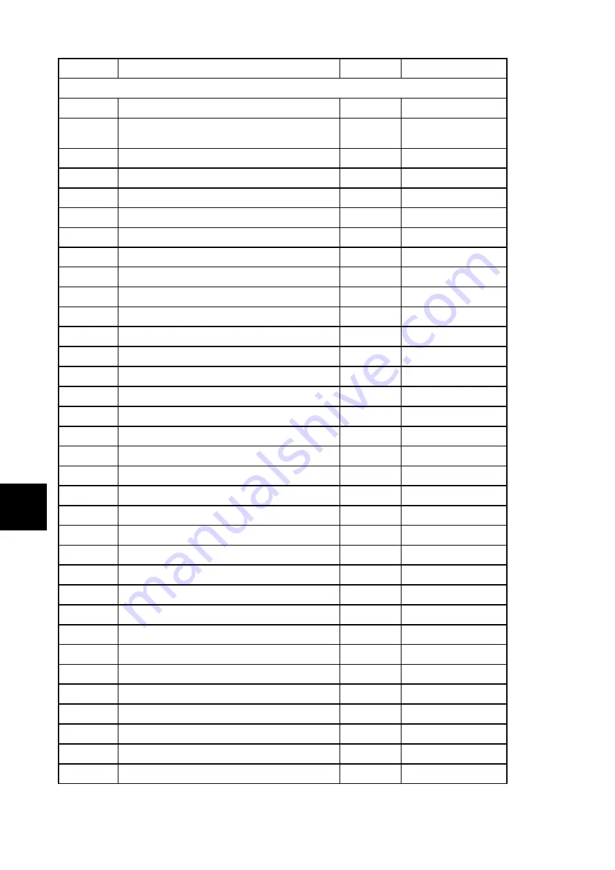
Replacement parts list HSP 6 537.08–WT RLU/PGI (without trim parts)

A1

Complete combustion chamber door/black

1 piece

0553808005300

A1

Complete combustion chamber door/
anthracite

1 piece

0553808015300

1

Ash-pan door/anthracite

1 piece

0553808005060

2

Ash pan/anthracite

1 piece

0553808005600

3

Burner cast/anthracite

1 piece

0553808005706

4

Protection grate

1 piece

0551908006709

5

Door contact switch

1 piece

0089500040005

6

Bottom temperature sensor

1 piece

0561008005543

7

Door hinge (complete)/anthracite

1 piece

0553808005400

8

Flame temperature sensor

1 piece

0553808005541

9

Combustion chamber cladding left

1 piece

0553808005040

10

Combustion chamber cladding back

1 piece

0553808005041

11

Holders of the fire-box lining le+ri/anthracite

2 piece

0553808005042

12

Combustion chamber cladding right

1 piece

0553808005039

13

Conecting pipe 3/4 L=670

1 piece

0553808005903

14

Hose Meniflex L=300

1 piece

0553808005315

15

Room temperature sensor

1 piece

0089500390005

16

Conecting pipe 3/4 L=1100

1 piece

0553808005902

17

Framework left

1 piece

0553808005021

18

Framework right

1 piece

0553808005022

19

Venting valve

1 piece

0088600005270

20

Seal

1 piece

0553808005026

21

Shielding of the cleaning orifice - Set

1 piece

0553808005025

22

Cleaning lever/anthracite

1 piece

0553808005023

23

Protective grille

1 piece

0553808005931

24

Seal, tank cover (1000 mm)

1 piece

0546608005189

25

Tank cover/anthracite

1 piece

0553808005190

26

Grip

1 piece

0089500940005

27

Operator console

1 piece

0571207005510

28

Cover hinge pins DIN 427 M5x18

1 piece

0553808005015

29

Conveyor

1 piece

0571207015060

30

Lower screw conveyor bearing

1 piece

0571207005026

31

Screw conveyor

1 piece

0571207005030

32

Collet

1 piece

0089000340009

Summary of Contents for HSP 6 537.08-WT RLU/PGI

Page 1: ...HSP 6 537 08 WT RLU PGI Equipment sheet Pellet stove with heat exchanger GB 0553708001403b Equipment sheet HSP 6 537 08 WT RLU PGI...

Page 2: ...he heating device or of an injury The note entitled Notice advises you on possible damage to your heating device The note entitled Important calls your attention to the information important for the o...

Page 3: ...tenance work 6 4 1 Cleaning of the ash pan once a week 6 4 2 Cleaning of the exchanger once a week 8 4 2 1 Vertical cleaning of the exchanger 8 4 2 2 Horizontal cleaning of the conduits of combustion...

Page 4: ......

Page 5: ...f storage container pellet tank about 32 kg Duration of burn with one charge min max about 15 h 60 h Permitted fuel Low dust wood pellets diameter 6 mm to Norm M 7135 DIN plus EN plus A1 length max 30...

Page 6: ...Dimensions GB 2 2 Dimensions 2 1 Dimensions...

Page 7: ...nnection of the exchanger Item Name A Heating water output outside thread G3 4 B Return water intake outside thread G3 4 C Outlet of the safety valve outside thread G1 2 D Filling of the circulation s...

Page 8: ...stion chamber function instruction Error F040 The whole combustion space must be cleaned after 30 hours operation at the latest or once a week The requirement to clean the fire box flickering of the d...

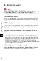
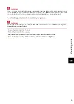
Page 9: ...ring in the pellet tank might possibly result This will destroy your device and is not covered in your guarantee WARNING Cleaning the combustion pot may only be done with a cooled down stove in OFF op...

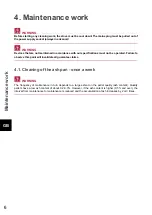
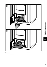
Page 10: ...fications must not be operated Failure to observe this point will invalidate all guarantee claims 4 1 Cleaning of the ash pan once a week WARNING The frequency of maintenance in turn depends to a larg...

Page 11: ...Maintenance work GB 7 Figure 1...

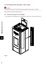
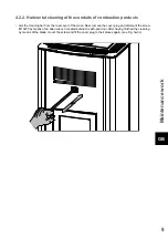
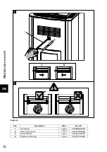
Page 12: ...to clean the conduits of combustion products and the exchanger once in a week Please perform the short time cleaning in two steps 4 2 1 Vertical cleaning of the exchanger For the purposes of vertical...

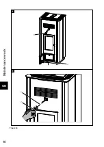
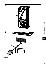
Page 13: ...cleaning bar from the rear cover of the stove Next remove the cover plug and dismount the screw M10x70 by means of an Allen wrench located behind the ash pan door After having finished the cleaning by...

Page 14: ...Maintenance work GB 10 Figure 3a...

Page 15: ...Maintenance work GB 11 Figure 3b...

Page 16: ...ce work GB 12 Figure 3c Pos Description Piece No PR 1 Cover plug 1 piece 0553808006180 2 Allen wrench 6mm 1 piece 9001700060005 3 Screw M10x70 1 piece 0030121000705 4 Drawbar of cleaning 1 piece 04333...

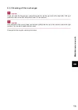
Page 17: ...s ducts at the latest after 1000 kg of pellets have been consumed Clean with a brush or an ash extractor CAUTION After completion of the cleaning make sure that when putting back the covers the seals...

Page 18: ...Maintenance work GB 14 Figure 4...

Page 19: ...Maintenance work GB 15 Figure 5 Removing the side wall...

Page 20: ...1 in the pellet tank may be removed Then clean the tank and the intake of the screw conveyor housing with a vacuum cleaner After cleaning it is essential to put back the protective grille When doing...

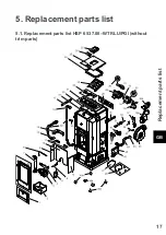
Page 21: ...Replacement parts list GB 17 5 Replacement parts list 5 1 Replacement parts list HSP 6 537 08 WT RLU PGI without trim parts...

Page 22: ...e ri anthracite 2 piece 0553808005042 12 Combustion chamber cladding right 1 piece 0553808005039 13 Conecting pipe 3 4 L 670 1 piece 0553808005903 14 Hose Meniflex L 300 1 piece 0553808005315 15 Room...

Page 23: ...5202 40 Outlets of the hydraulic system cock Ms Cross inserts set 1 piece 0088600000055 41 OC 2 piece 0089500080005 42 Flue gas thermosensor 1 piece 0561008005540 43 Conecting pipe L 550 1 piece 05538...

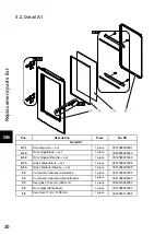
Page 24: ...cite set 1 piece 0553808005340 A1 3 Glass holder black set 1 piece 0551908035308 A1 3 Glass holder anthracite set 1 piece 0551908005308 52 Combustion chamber door black 1 piece 0541908007220 52 Combus...

Page 25: ...piece 0553808006140 56 58 Side wall left right white 2 piece 0553808016140 57 Front plate anthracite 1 piece 0553808016120 57 Front plate anthracite black 1 piece 0553808006120 59 Cover plate anthraci...

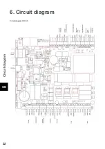
Page 26: ...Circuit diagram GB 22 6 Circuit diagram Circuit diagram IO 33 6...

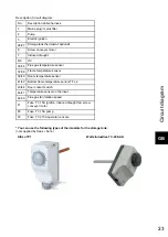
Page 27: ...7 38 Flame temperature sensor 39 40 Room temperature sensor 41 42 Bottom flame temperature sensor TFL 2 43 44 Door contact switch 46 47 Temperature sensor on the input 48 50 Flue gas fan rotation spee...

Page 28: ......
Reviews: