background image

10 


Figure 18:

 Burner with burner rings 

1 - 6 

Combustion air hole rows  

Oil inlet 

Bead 

Lower burner ring  

10 

Support pin 

11 

Upper burner ring 

 
Also ascertain the correct seat of the draught deflection 
(see  Figures  1 + 2). This is usually inserted already at 
the  factory  but  may  come  loose  from  the  suspension 
due to transport vibrations. It must also be correctly re-
installed after cleaning and maintenance operations.  
 
A primary-air limiter (PAL, see Figure 19) is installed in 
your  oil  stove,  which  compensates  delivery  pressures 
above  20  Pa  so  that  economical  heating  is  possible 
also  with  high  delivery  pressure  (chimney  draught). 
Please  check  the  perfect  operation  of  the  PAL  or 
draught  limiter.  To  this  end  observe  the  instructions  in 
Chapter 12.3 “Maintenance of primary air limiter”. 


Bottom 

Figure 19: Primary air limiter (PAL)


Primary air limiter 

Pendulum flap 

 
During  initial  start-up  the  oil  stove  must  be  heated 
carefully, i.e. the output controller should be set to 2 to 
3  during  the  first  hour,  after  which  normal  heating  can 
commence.  The  materials  of  your  new  oil  stove  must 
get  slowly  used  to  the  heat  development.  Through 
careful  initial  heating  you  will  avoid  damages  to  paint 
and  distortion  of  material.  Possible  development  of 
smell through post-drying of the protective painting will 
disappear  after  a short time. Thoroughly air the rooms 
during the paint curing time several times. 
 
Open  the  tank  shut-off  valve  2  to  3  turns  anti-
clockwise. If the appliance is connected to a central oil 
supply, open the quick closing valve (90° turn). 
 

Important: 

Before  starting  your  appliance  for  the  first 

time  you  will  have  to 

lift

  the 

safety  lever 

(controller 

latch)  of  the  oil  controller  (make:  TOBY  DVR,  see 
Figure 20), after which the lever will drop automatically. 

This will enable the oil to flow from the oil tank or from 
the central oil supply to the oil controller. 
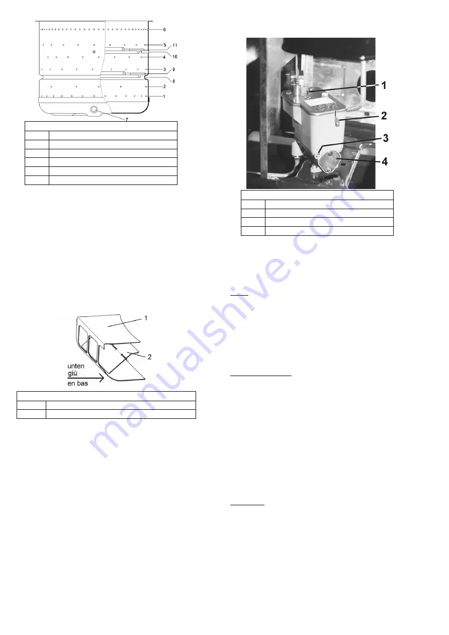


Figure 20:

 Oil controller 

Control pin  

Safety lever (controller latch) 

Oil drain plug 

Filter cover with seal 

 
When  igniting  during  initial  start-up,  oil  controller  and 
lines  must  first  be  allowed  to  fill  with  oil.  This  takes 
approximately  3  minutes.  With  each  subsequent  start-
up, oil will flow into the burner even after approximately 
10 

– 15 seconds. 

Note:  With  a  new  appliance,  wax  strips  are  better 
suited for lighting than liquid oil stove igniters since the 
surface  of  the  burner  insert  base  is  still  very  smooth. 
After  several  starts,  fine  crusts  will  form  at  the  base 
which  increase  the  surface  area,  improving  oil 
evaporation  in  the  burner.  At  that  stage  you  can  start 
using liquid oil stove igniters without restriction. 

11.4.  Igniting and normal operating mode 

Note  at  all  times:  If  the  appliance  has  already  been 
heated,  the  oil  stove  must  only  be  started  up  again 
when  the burner insert has cooled down (hand warm). 
Otherwise there is a risk of a detonation with additional 
consequential damages. 
 
1. 

Turn output controller anti-clockwise to position 
“6” by overcoming slight noticeable resistance. 
On appliances with electric ignition, this serves 
to  automatically  activate  the  latter.  When  oil 
enters  the  burner,  immediately  turn  output 
controller  to  position  “1”.  The  marking  next  to 
the  output  controller  indicates  the  set  output 
stage. 


CAUTION

:  Do  not  allow  the  burner  to  be  flooded! 

Please  ensure  that  only  a small amount of oil is in the 
burner pot when igniting. If there is a larger amount of 
oil  in  the  burner,  you  will  have  to  absorb  the  oil  for 
instance  using  an  entire  roll  of  toilet  paper  since  the 
burner  base  must  only  be  wet  but  not  flooded.  A 
flooded burner must not be ignited! 
 
2. 

On  appliances  without  electric  ignition  the  oil 
can  now  be  lit  by  means  of  bent  wax  strips, 

Summary of Contents for Ibiza 469.50

Page 1: ...t stoves Tiled and slow burning stoves for wood and coal Slow burning and auxiliary stoves for wood coal and oil Fireplace inserts for wood Electric fireplaces Accessories for stove and fireplace Accessories for central oil supply Air humidifiers Haas Sohn Sales in Germany Ofentechnik GmbH Haas Sohn Ofentechnik GmbH Urstein Nord 67 Zur Dornheck 8 A 5412 Puch D 35764 Sinn eMail office haassohn com ...

Page 2: ...or safe operation and for possibly occurring faults and their remedy In order to comply with the Appliance Safety Act these operating instructions must therefore be accessible to the user of the appliance at all times Keep these instructions therefore in a safe place We can provide warranty on our products only if you comply with the following guidelines of these installation and operating instruc...

Page 3: ...tove unobstructed even during the operation of exhaust systems bathroom exhaust fans kitchen extractors etc in your home or in any other connected rooms Stove operation is not jeopardized when the systems only circulate the air within a room or the systems are equipped with safety installations that automatically and reliably prevent vacuum in the installation room It is imperative that you should...

Page 4: ... 181072 181072 181072 18 Control linkage 181059 181059 181059 19 Öil controller 182036 182036 182036 20 Oil inlet spigot with cleaning crank 173137 173137 173137 21 Oil line oil controller burner 181073 181073 182974 22 Tank insert lid 127221 127221 127221 23 Tank strainer 127211 127211 127211 24 Oil level gauge floating ball 127230 127230 127230 27 Fire chamber door 182569 181348 182514 28 Oil gu...

Page 5: ... room tank Article No 1 straight ferrule screw connection 8x8 102151 1 flexible fuel oil hose 50cm 75 cm 100 cm 104212 104213 104214 1 pressure controller 8x8 105170 1 oil pump z B 100280 1 quick closing valve 105146 Additional accessories angular ferrule screw connections T ferrule screw connections reducing screw connections oil flow meter filter change over valves etc are always available from ...

Page 6: ...right of the flue pipe spigot are located in the rear wall of the stove corresponding with the holes of the tank bracket Insert 4 snap on clips see Figures 5 6 either in the 4 left or right slits L or R 4 Now hook the tank bracket into the top and bottom snap on clips see Figure 7 Figure 7 Installing the tank bracket 1 Tank bracket 2 Rear wall 3 Snap on clip Figure 8 Assembly of the insert angles ...

Page 7: ...To do so remove the prepared opening in the rear wall by breaking out the sheet metal and insert the oil guide plate see Figure 2 6 A For emptying or cleaning the oil pan can be removed either from the front or from the rear Figure 11 Ibiza 469 50 Installation of oil guide plate 1 Oil guide plate 2 Recess 3 Rear wall 8 Conversion instructions for the model Viking 468 50 to vertical flue pipe conne...

Page 8: ...lue pipe does not protrude into the free cross section of the chimney see Figure 13 To insert the pipe in the chimney the use of wall lining is recommended Flue pipe connections of neighbouring rooms must be connected to the chimney with at least a 50 cm stagger see figure 13 Wrong With longer flue gas pipe configuration maximum 3 m horizontal sections must be avoided piping that rises in the dire...

Page 9: ...oned above such as petrol benzene engine lubricating oil waste oil or solvents must never be burnt in your heating appliance Neither should you use any additives or other additional substances with your fuel oil Notes 1 Store fuel oil only in tanks intended for this purpose and in suitable storage rooms while observing the regulations of your responsible fire protection authority or building autho...

Page 10: ... the lever will drop automatically This will enable the oil to flow from the oil tank or from the central oil supply to the oil controller Figure 20 Oil controller 1 Control pin 2 Safety lever controller latch 3 Oil drain plug 4 Filter cover with seal When igniting during initial start up oil controller and lines must first be allowed to fill with oil This takes approximately 3 minutes With each s...

Page 11: ...into the burner is not damaged Otherwise the electric ignition function will be detrimentally affected For some maintenance operations you will have to remove the inspection panel the rear wall Viking or sidewall Ibiza see Figures 1 2 On model Viking 468 50 it is only required to lift the inspection panel see Figure 1 below the fire chamber door a few millimetres before unhooking possible without ...

Page 12: ...n either the tank shut off valve or with central oil supply the quick closing valve Remove water in the heating appliance as follows 1 Drain oil from the oil controller by opening the drain plug and the filter cover 2 Unscrew connection line from the oil controller to the burner open end wrench 14 and 17 and drain When installing the oil line ensure that the screw connections are tightened careful...

Page 13: ...crews of the retaining plate see figure 24 and remove the retaining plate with a short anti clockwise movement 4 Pull the ignition bar from the burner by lightly turning 90 5 It is imperative to secure the glass fibre seal approximately 2 3 mm diameter see Figure 24 around the new ignition bar to completely seal the hole 6 Place the tension spring on the ignition bar 7 Install the ignition bar in ...

Page 14: ...chimney sweeper The oil stove heat output is excessive The seals on the burner on fire chamber door electric ignition bar pressure equalisation plate are defective Replace seals Pressure equalisation plate is not supported properly Carefully position pressure equalisation plate The output controller is set too high Set output controller lower The delivery pressure chimney draught is too high Clari...

Page 15: ...onnection of the appliance insufficient or excessive chimney draft incorrectly performed repair work or other especially subsequent changes to the fireplace or flue gas line stove pipe and chimney failure to observe the installation and operating instructions as well as installation of spare parts and accessories not included in our lists use of unsuitable or contaminated fuels admixing corrosion ...

Page 16: ...instructions Our tip Transfer the data from the nameplate of the stove in Figure 24 If no remark concerning model and manufacturing numbers is provided on page 1 of these instructions please enter them there In this way you will always have immediate access to all important data H A A S S O H N Ofentechnik GmbH Herborner Straße 7 9 35764 Sinn MODEL NUMBER MANUFACTURING NO RATED HEAT OUTPUT W DIN R...

Reviews: