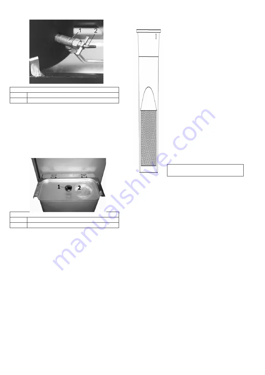
background image

12 

Figure 23:

 Plastic filter  


Figure 21


Inlet spigot 

Cleaning crank 


12.2.  Cleaning the oil-carrying parts 

Before working on the oil controller (make: TOBY DVR) 
it  is  always  necessary  to  close  the  tank  shut-off  valve 
(see  Figure  22)  or,  with  central  oil  supply,  the  quick 
closing  valve  before  the  stove!  You  can  either  place  a 
shallow vessel under the oil controller for collecting the 
oil or allow the oil to drain into the existing oil pan. 
Dirt in the oil controller can be removed as follows: 


Figure 22: Oil tank


Tank shut-off valve 

Tank insert lid 

 
1.  Remove filter cover on the oil controller (2 screws) 

and remove filter seal and collect oil (Figure 20). 

2.  Remove  plastic  filter  and  immerse  in  hot  water 

(max. 60°C 

– do not use boiling water!), for several 

minutes,  clean  with  a  brush  if  required.  Please  do 
not use paraffin or petrol for cleaning the filter since 
residue  containing  paraffin  in  the  strainer  can  only 
be removed with hot water. 

3.  Shake the filter and allow to dry. 
4.  Slide the filter back into the controller and reattach 

the  filter  seal  and  the  filter  cover  using  the  two 
screws. 

5.  Re-establish  the  oil  supply  to  the  oil  controller: 

open  either  the  tank  shut-off  valve  or,  with  central 
oil supply, the quick closing valve. 

 
Remove water in the heating appliance as follows:  
1.  Drain oil from the oil controller by opening the drain 
plug and the filter cover.  
2.  Unscrew  connection  line  from  the  oil  controller  to 
the  burner  (open-end  wrench  14  and  17)  and  drain. 
When  installing  the  oil  line,  ensure  that  the  screw 

connections  are  tightened  carefully  without  excessive 
force to avoid damaging the threads resulting in leaks. 

3.  With  water  in  the  tank,  keep  the 
tank  shut-off  valve  open  with  opened 
filter cover until pure fuel oil runs out. 
 
In  rare  cases  it  may  happen  that  the 
dosing bar in the oil controller becomes 
dirty,  obstructing  or  even  entirely 
interrupting  the  oil  flow.  If  applicable, 
this  can  be  rectified  as  follows:  Set 
output  controller  to  maximum  position 
“6”  and  vigorously  tap  on  the  control 
pin  on  the  oil  controller  cover  (see 
Figure  20).  After  this,  turn  the  output 
controller back to  “0”. 
 
You  might  have  to  push  the  safety 
lever  (controller  latch)  of  the  oil 
controller up (see Figure 20) to release 
the  oil  supply  to  the  controller  (see 
Chapter 11.3.). 
 
You  should  also  clean  the  filter  in  the 
filler neck of the tank from time to time 
(see Figures 22 + 23). To do so, simply 
remove  the  tank  lid  and  remove  the 
filter.  After  this,  proceed  as  described 
in  paragraph  2.  Cleaning  the  plastic 
filter. 


Summary of Contents for Ibiza 469.50

Page 1: ...t stoves Tiled and slow burning stoves for wood and coal Slow burning and auxiliary stoves for wood coal and oil Fireplace inserts for wood Electric fireplaces Accessories for stove and fireplace Accessories for central oil supply Air humidifiers Haas Sohn Sales in Germany Ofentechnik GmbH Haas Sohn Ofentechnik GmbH Urstein Nord 67 Zur Dornheck 8 A 5412 Puch D 35764 Sinn eMail office haassohn com ...

Page 2: ...or safe operation and for possibly occurring faults and their remedy In order to comply with the Appliance Safety Act these operating instructions must therefore be accessible to the user of the appliance at all times Keep these instructions therefore in a safe place We can provide warranty on our products only if you comply with the following guidelines of these installation and operating instruc...

Page 3: ...tove unobstructed even during the operation of exhaust systems bathroom exhaust fans kitchen extractors etc in your home or in any other connected rooms Stove operation is not jeopardized when the systems only circulate the air within a room or the systems are equipped with safety installations that automatically and reliably prevent vacuum in the installation room It is imperative that you should...

Page 4: ... 181072 181072 181072 18 Control linkage 181059 181059 181059 19 Öil controller 182036 182036 182036 20 Oil inlet spigot with cleaning crank 173137 173137 173137 21 Oil line oil controller burner 181073 181073 182974 22 Tank insert lid 127221 127221 127221 23 Tank strainer 127211 127211 127211 24 Oil level gauge floating ball 127230 127230 127230 27 Fire chamber door 182569 181348 182514 28 Oil gu...

Page 5: ... room tank Article No 1 straight ferrule screw connection 8x8 102151 1 flexible fuel oil hose 50cm 75 cm 100 cm 104212 104213 104214 1 pressure controller 8x8 105170 1 oil pump z B 100280 1 quick closing valve 105146 Additional accessories angular ferrule screw connections T ferrule screw connections reducing screw connections oil flow meter filter change over valves etc are always available from ...

Page 6: ...right of the flue pipe spigot are located in the rear wall of the stove corresponding with the holes of the tank bracket Insert 4 snap on clips see Figures 5 6 either in the 4 left or right slits L or R 4 Now hook the tank bracket into the top and bottom snap on clips see Figure 7 Figure 7 Installing the tank bracket 1 Tank bracket 2 Rear wall 3 Snap on clip Figure 8 Assembly of the insert angles ...

Page 7: ...To do so remove the prepared opening in the rear wall by breaking out the sheet metal and insert the oil guide plate see Figure 2 6 A For emptying or cleaning the oil pan can be removed either from the front or from the rear Figure 11 Ibiza 469 50 Installation of oil guide plate 1 Oil guide plate 2 Recess 3 Rear wall 8 Conversion instructions for the model Viking 468 50 to vertical flue pipe conne...

Page 8: ...lue pipe does not protrude into the free cross section of the chimney see Figure 13 To insert the pipe in the chimney the use of wall lining is recommended Flue pipe connections of neighbouring rooms must be connected to the chimney with at least a 50 cm stagger see figure 13 Wrong With longer flue gas pipe configuration maximum 3 m horizontal sections must be avoided piping that rises in the dire...

Page 9: ...oned above such as petrol benzene engine lubricating oil waste oil or solvents must never be burnt in your heating appliance Neither should you use any additives or other additional substances with your fuel oil Notes 1 Store fuel oil only in tanks intended for this purpose and in suitable storage rooms while observing the regulations of your responsible fire protection authority or building autho...

Page 10: ... the lever will drop automatically This will enable the oil to flow from the oil tank or from the central oil supply to the oil controller Figure 20 Oil controller 1 Control pin 2 Safety lever controller latch 3 Oil drain plug 4 Filter cover with seal When igniting during initial start up oil controller and lines must first be allowed to fill with oil This takes approximately 3 minutes With each s...

Page 11: ...into the burner is not damaged Otherwise the electric ignition function will be detrimentally affected For some maintenance operations you will have to remove the inspection panel the rear wall Viking or sidewall Ibiza see Figures 1 2 On model Viking 468 50 it is only required to lift the inspection panel see Figure 1 below the fire chamber door a few millimetres before unhooking possible without ...

Page 12: ...n either the tank shut off valve or with central oil supply the quick closing valve Remove water in the heating appliance as follows 1 Drain oil from the oil controller by opening the drain plug and the filter cover 2 Unscrew connection line from the oil controller to the burner open end wrench 14 and 17 and drain When installing the oil line ensure that the screw connections are tightened careful...

Page 13: ...crews of the retaining plate see figure 24 and remove the retaining plate with a short anti clockwise movement 4 Pull the ignition bar from the burner by lightly turning 90 5 It is imperative to secure the glass fibre seal approximately 2 3 mm diameter see Figure 24 around the new ignition bar to completely seal the hole 6 Place the tension spring on the ignition bar 7 Install the ignition bar in ...

Page 14: ...chimney sweeper The oil stove heat output is excessive The seals on the burner on fire chamber door electric ignition bar pressure equalisation plate are defective Replace seals Pressure equalisation plate is not supported properly Carefully position pressure equalisation plate The output controller is set too high Set output controller lower The delivery pressure chimney draught is too high Clari...

Page 15: ...onnection of the appliance insufficient or excessive chimney draft incorrectly performed repair work or other especially subsequent changes to the fireplace or flue gas line stove pipe and chimney failure to observe the installation and operating instructions as well as installation of spare parts and accessories not included in our lists use of unsuitable or contaminated fuels admixing corrosion ...

Page 16: ...instructions Our tip Transfer the data from the nameplate of the stove in Figure 24 If no remark concerning model and manufacturing numbers is provided on page 1 of these instructions please enter them there In this way you will always have immediate access to all important data H A A S S O H N Ofentechnik GmbH Herborner Straße 7 9 35764 Sinn MODEL NUMBER MANUFACTURING NO RATED HEAT OUTPUT W DIN R...

Reviews: