


2. General information, safety instructions
Always observe the valid official regulations concerning
fire protection applicable in your country and the building
regulations applicable at the place of installation and
consult the responsible district master chimney-sweeper
when installing your stove. He will check the proper
connection of the appliance to the chimney. Obviously,
fuel oil will also have to be stored in accordance with the
regulations of the fire protection authorities and the
building authorities.
Your oil stove has been subjected to all tests required by
the legislator and it meets the specified requirements in
terms of design and operation, efficiency, safety
equipment and flue gas emissions.
Your stove described in these instructions has been tested
in accordance with DIN EN
1 (“heating stoves for liquid
fuels with evaporation burners and chimney connection”).
Oil stoves may be connected to a chimney with multiple
connections if such is permitted by the chimney dimension
(e.g. according to DIN 4705 Part 2).
Because of the necessary combustion supply air, windows
and doors in the installation room must not seal too tightly.
Adequate fresh air supply to the installation room of your
appliance must be ensured. The necessary minimum
amount of air must be able to flow to the oil stove
unobstructed even during the operation of exhaust
systems (bathroom exhaust fans, kitchen extractors etc.)
in your home or in any other connected rooms. Stove
operation is not jeopardized when the systems only
circulate the air within a room or the systems are equipped
with safety installations that automatically and reliably
prevent vacuum in the installation room. It is imperative
that you should clarify the adequate combustion air supply
with your master chimney-sweeper.
Please note that heat energy is liberated when burning
fuel materials which can heat the surfaces of the heating
appliance (doors, door and control handles, view window
panes, sidewalls, front wall, flue pipes). For this reason,
employ the necessary care when handling the appliance.
Do not wear any loose or easily combustible clothing when
heating up your stove!
Please note at all times: If the appliance has already been
heated the oil stove must only be restarted once the
burner insert has cooled down (hand warm) to avoid the
risk of a detonation with additional consequential
damages.
3. Data for calculating the chimney dimension
according to DIN 4705 Part
Models
Rate
d h
ea
t l
oa
d [
k
W
]
F
lue
ga
s
ma
s
s
fl
ow [g
/s
]
F
lue
ga
s
te
mp
erature at
rate
d h
ea
t l
oa
d [
°C]
Mi
ni
mu
m d
el
iv
ery
pres
s
ure at
rate
d h
ea
t
loa
d [
P
a]
Mi
ni
mu
m d
el
iv
ery
pres
s
ure at
0.8
ti
me
s
rate
d h
ea
t l
oa
d [
P
a]
F
lue
pi
pe
di
am
ete
r [m
m]
Ibiza 469.50
5,5 3,60 290
14
11
120
Viking 468.50 5,5 3,60 290
14
11
120
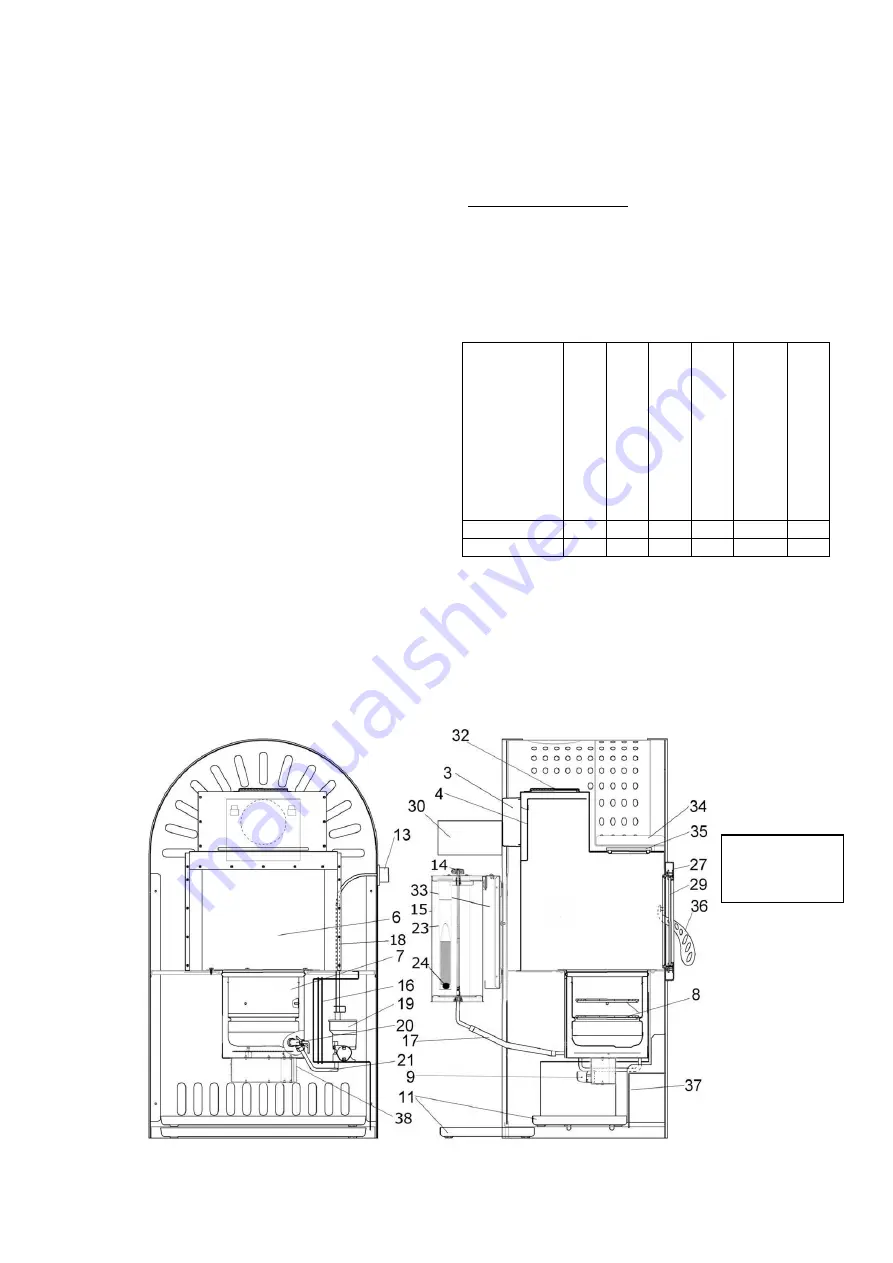
4.
Construction of the HAAS+SOHN oil stoves
Figure 1:
Oil stove
Viking 468.50


