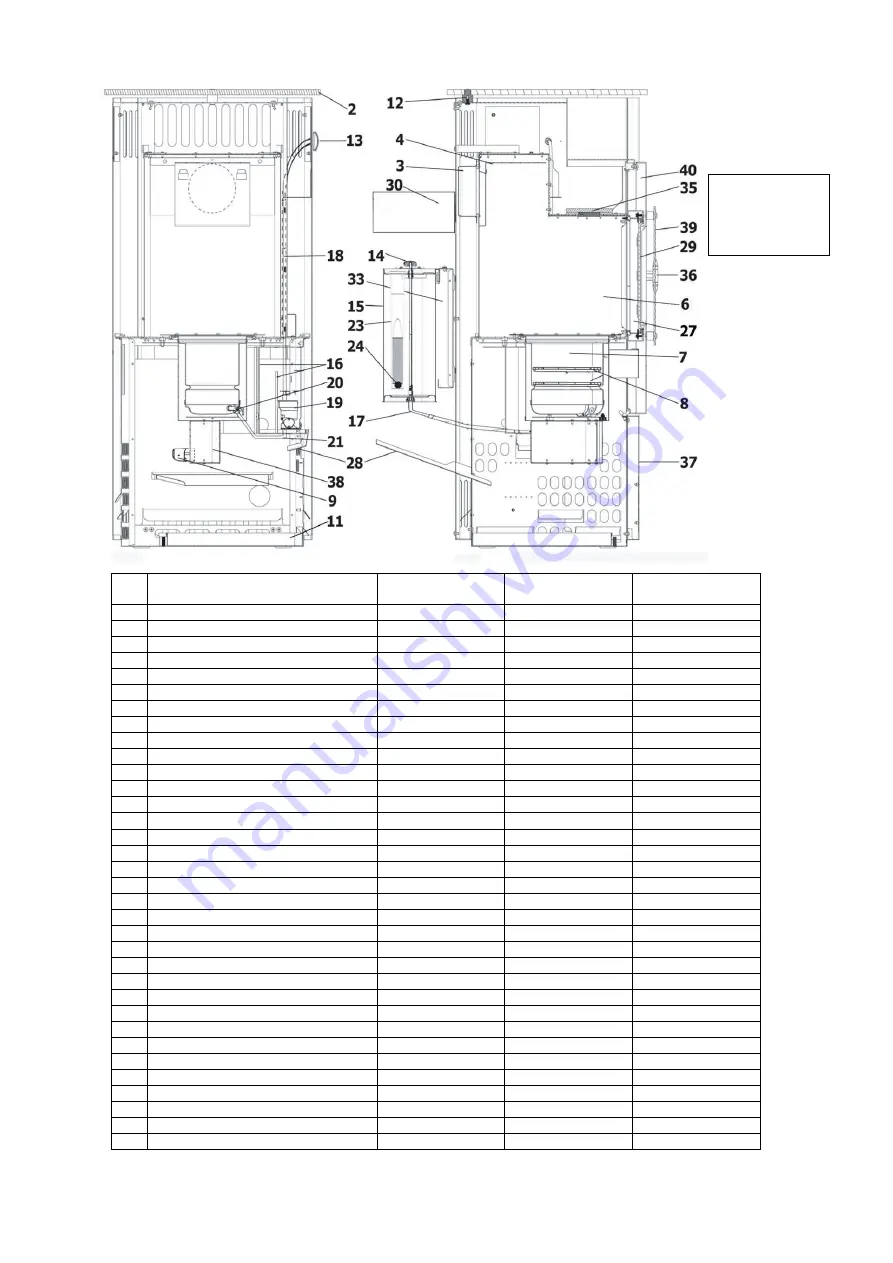
background image


Figure 2:  

Oil stove Ibiza 
469.50 
 

No. 

Designation 

Art. No. Viking 

468.50 anth. 

Art. No. Viking 

468.50 blue 

Art. No. Ibiza 

469.50 

Cover plate 

182546 

Flue pipe spigot  

199025 

199025 

199025 

Draft baffle 

181535 

181535 

181535 

Combustion chamber 


Burner (burner pot) 


Upper and lower burner ring 

129211 

129211 

129211 

Combustion air limiter (CAL) 

138510 

138510 

138510 

11 

Öil pan 

160542 

160542 

182990 

12 

Support bearing 


13 

Output controller 

198004 

198004 

198004 

14 

Tank shut-off valve knob 

153627 

153627 

153627 

15 

Oiltank 

182996 

182996 

182996 

16 

Screen wall 


17 

Oil line tank 

– oil controller 

181072 

181072 

181072 

18 

Control linkage 

181059 

181059 

181059 

19 

Öil controller 

182036 

182036 

182036 

20 

Oil inlet spigot with cleaning crank 

173137 

173137 

173137 

21 

Oil line oil controller - burner 

181073 

181073 

182974 

22 

Tank insert lid 

127221 

127221 

127221 

23 

Tank strainer 

127211 

127211 

127211 

24 

Oil level gauge floating ball 

127230 

127230 

127230 

27 

Fire chamber door 

182569 

181348 

182514 

28 

Oil guide plate 

182994 

29 

View window 

182538 

181538 

182544 

30 

Tank screen panel 


32 

Pipe spigot lid 

198013 

198013 

33 

Tank bracket 


34 

Warming compartment insert 

181077 

181077 

35 

Pressure compensation plate 

182462 

182462 

182462 

36 

Door handle 

182219 

182219 

702500 

37 

Inspection cover 

181620 

181153 

182987 

38 

Preheating compartment 

182350 

182460 

182350 

39 

Glass primary door 

182545 

40 

Primary door 

182537 


Summary of Contents for Ibiza 469.50

Page 1: ...t stoves Tiled and slow burning stoves for wood and coal Slow burning and auxiliary stoves for wood coal and oil Fireplace inserts for wood Electric fireplaces Accessories for stove and fireplace Accessories for central oil supply Air humidifiers Haas Sohn Sales in Germany Ofentechnik GmbH Haas Sohn Ofentechnik GmbH Urstein Nord 67 Zur Dornheck 8 A 5412 Puch D 35764 Sinn eMail office haassohn com ...

Page 2: ...or safe operation and for possibly occurring faults and their remedy In order to comply with the Appliance Safety Act these operating instructions must therefore be accessible to the user of the appliance at all times Keep these instructions therefore in a safe place We can provide warranty on our products only if you comply with the following guidelines of these installation and operating instruc...

Page 3: ...tove unobstructed even during the operation of exhaust systems bathroom exhaust fans kitchen extractors etc in your home or in any other connected rooms Stove operation is not jeopardized when the systems only circulate the air within a room or the systems are equipped with safety installations that automatically and reliably prevent vacuum in the installation room It is imperative that you should...

Page 4: ... 181072 181072 181072 18 Control linkage 181059 181059 181059 19 Öil controller 182036 182036 182036 20 Oil inlet spigot with cleaning crank 173137 173137 173137 21 Oil line oil controller burner 181073 181073 182974 22 Tank insert lid 127221 127221 127221 23 Tank strainer 127211 127211 127211 24 Oil level gauge floating ball 127230 127230 127230 27 Fire chamber door 182569 181348 182514 28 Oil gu...

Page 5: ... room tank Article No 1 straight ferrule screw connection 8x8 102151 1 flexible fuel oil hose 50cm 75 cm 100 cm 104212 104213 104214 1 pressure controller 8x8 105170 1 oil pump z B 100280 1 quick closing valve 105146 Additional accessories angular ferrule screw connections T ferrule screw connections reducing screw connections oil flow meter filter change over valves etc are always available from ...

Page 6: ...right of the flue pipe spigot are located in the rear wall of the stove corresponding with the holes of the tank bracket Insert 4 snap on clips see Figures 5 6 either in the 4 left or right slits L or R 4 Now hook the tank bracket into the top and bottom snap on clips see Figure 7 Figure 7 Installing the tank bracket 1 Tank bracket 2 Rear wall 3 Snap on clip Figure 8 Assembly of the insert angles ...

Page 7: ...To do so remove the prepared opening in the rear wall by breaking out the sheet metal and insert the oil guide plate see Figure 2 6 A For emptying or cleaning the oil pan can be removed either from the front or from the rear Figure 11 Ibiza 469 50 Installation of oil guide plate 1 Oil guide plate 2 Recess 3 Rear wall 8 Conversion instructions for the model Viking 468 50 to vertical flue pipe conne...

Page 8: ...lue pipe does not protrude into the free cross section of the chimney see Figure 13 To insert the pipe in the chimney the use of wall lining is recommended Flue pipe connections of neighbouring rooms must be connected to the chimney with at least a 50 cm stagger see figure 13 Wrong With longer flue gas pipe configuration maximum 3 m horizontal sections must be avoided piping that rises in the dire...

Page 9: ...oned above such as petrol benzene engine lubricating oil waste oil or solvents must never be burnt in your heating appliance Neither should you use any additives or other additional substances with your fuel oil Notes 1 Store fuel oil only in tanks intended for this purpose and in suitable storage rooms while observing the regulations of your responsible fire protection authority or building autho...

Page 10: ... the lever will drop automatically This will enable the oil to flow from the oil tank or from the central oil supply to the oil controller Figure 20 Oil controller 1 Control pin 2 Safety lever controller latch 3 Oil drain plug 4 Filter cover with seal When igniting during initial start up oil controller and lines must first be allowed to fill with oil This takes approximately 3 minutes With each s...

Page 11: ...into the burner is not damaged Otherwise the electric ignition function will be detrimentally affected For some maintenance operations you will have to remove the inspection panel the rear wall Viking or sidewall Ibiza see Figures 1 2 On model Viking 468 50 it is only required to lift the inspection panel see Figure 1 below the fire chamber door a few millimetres before unhooking possible without ...

Page 12: ...n either the tank shut off valve or with central oil supply the quick closing valve Remove water in the heating appliance as follows 1 Drain oil from the oil controller by opening the drain plug and the filter cover 2 Unscrew connection line from the oil controller to the burner open end wrench 14 and 17 and drain When installing the oil line ensure that the screw connections are tightened careful...

Page 13: ...crews of the retaining plate see figure 24 and remove the retaining plate with a short anti clockwise movement 4 Pull the ignition bar from the burner by lightly turning 90 5 It is imperative to secure the glass fibre seal approximately 2 3 mm diameter see Figure 24 around the new ignition bar to completely seal the hole 6 Place the tension spring on the ignition bar 7 Install the ignition bar in ...

Page 14: ...chimney sweeper The oil stove heat output is excessive The seals on the burner on fire chamber door electric ignition bar pressure equalisation plate are defective Replace seals Pressure equalisation plate is not supported properly Carefully position pressure equalisation plate The output controller is set too high Set output controller lower The delivery pressure chimney draught is too high Clari...

Page 15: ...onnection of the appliance insufficient or excessive chimney draft incorrectly performed repair work or other especially subsequent changes to the fireplace or flue gas line stove pipe and chimney failure to observe the installation and operating instructions as well as installation of spare parts and accessories not included in our lists use of unsuitable or contaminated fuels admixing corrosion ...

Page 16: ...instructions Our tip Transfer the data from the nameplate of the stove in Figure 24 If no remark concerning model and manufacturing numbers is provided on page 1 of these instructions please enter them there In this way you will always have immediate access to all important data H A A S S O H N Ofentechnik GmbH Herborner Straße 7 9 35764 Sinn MODEL NUMBER MANUFACTURING NO RATED HEAT OUTPUT W DIN R...

Reviews: