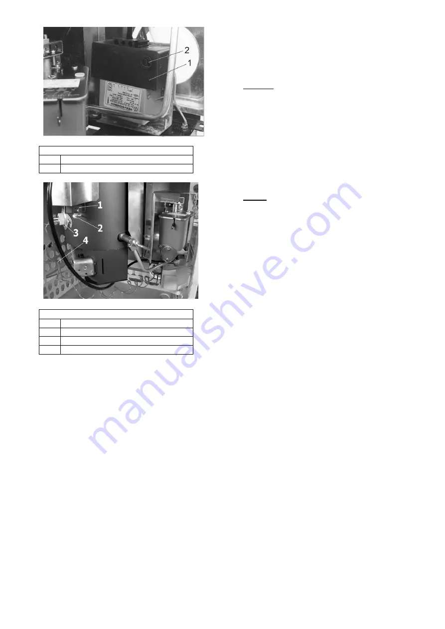
background image


Figure 16:

 Ignition transformer 

Ignition transformer 

Screw cap with microfuse 


Figure 17:

 electric ignition 

Bimetal switch 

Adjusting screw 

Ignition bar with terminals 

Supply line 

 
In  operation  the  electric  ignition  has  a  power 
consumption  of  63  watt  (see  name plate). The electric 
ignition  is  only  activated  when  the  output  controller  of 
the oil stove is set to an output stage between “1” and 
“6”.  However,  when  the  inner  stove  of  the  appliance 
has  heated  up  sufficiently  (this  is  the  case  even  a  few 
minutes after the start), the electric ignition is switched 
off  automatically  with  the  bimetal  switch  (see  Figure 
17).  When  the  oil  stove  is  hot  or  the  output  controller 
set to “0”, the appliance does not consume any electric 
power  and  does  not  therefore  use  up  any  electric 
current. 
 

11.  Oil stove operation 

The  oil  stove  must  only  be  started  by  adults.  Never 
allow  children  to be  present  near  the  oil  stove  on their 
own.  The  oil  stove  must  only  be  used  in  accordance 
with these operating instructions. 
 
Please  check  the  correct  seat  of  the  pressure 
equalisation plate (see Figure 2) before start-up. 


Please  observe  the  safety  instructions  provided  in 
Chapter 2. 

11.1.  Suitable fuels 

Only extra light fuel oil (ELFO) according to DIN 51603 
(or  the  standard  applicable  in  your  country)  is  suitable 
and  allowed  for  firing  in  your  oil  stove.  This  is  pointed 
out both on the appliance plate and on the screw cap of 
your oil tank (“use only special stove fuel oil”). 

 
Caution: 

Not  every  mineral  fuel  oil  can  be  burnt  in  your 
appliance.  Use  only  proven  brand  fuel  oils  in  your  oil 
stove. Unsuitable oils and contaminated fuel oils cause 
operating  problems.  Dirt  and  soot  accumulation  of  the 
stove, clogging the oil controller and the pipe- lines. 
 
Flammable  liquids  other  than  those  mentioned  above 
such  as  petrol,  benzene,  engine  lubricating  oil,  waste 
oil  or  solvents  must 

never 

be  burnt  in  your  heating 

appliance.  Neither  should  you  use  any  additives  or 
other additional substances with your fuel oil.


Notes: 

1. Store fuel oil only in tanks intended for this purpose 
and  in  suitable  storage  rooms,  while  observing  the 
regulations  of  your  responsible  fire  protection authority 
or building authority. 
2.  The  fuel  oil  storage  temperature  should  not  be 
significantly  lower  than  0°C.  Otherwise  paraffin  could 
settle  out  and  result  in  filter  repositioning.    Low 
temperatures  also  have  an  unfavourable  effect  on  the 
viscosity and the flow characteristics of fuel oil. If frost-
free  storage  of  fuel  oil  is  not  possible, we  recommend 
intermediate storage of the fuel oil in the filling can in a 
heated room before filling it into the oil stove tank. 
 

11.2.  Filling the oil tank 

Remove the screw cap before filling. Fill the oil in using 
a  spout  can.  Ensure  that  the  oil  is  not  filled  in  too 
rapidly  and  that  no  oil  is  spilt.  Please  close  the  screw 
cap again after filling. Note: please remember that cold 
fuel  oil  from  the  cellar  will  expand  with  rising 
temperature.  Do  not  therefore  fill  the  tank  to 
overflowing. 
 

11.3.  Initial start-up of your oil stove 

Prior  to  initial  start-up,  remove  any  adhesive  stickers, 
packaging  and  all  accessory  components  from  the 
firing chamber. 
Please  verify  that  the  enclosed  oil  pan  is  positioned 
exactly under the oil-carrying components (oil controller 
and oil lines) in its correct position as intended. 
Also  verify  that  both  burner  rings  (made  of  cast  iron) 
are  correctly  positioned  in  the  firing  chamber 
(horizontal  position).  The  firing  chamber  is  accessible 
through the firing chamber door. 


The  lower  burner  ring  must  rest  on  the  bead  of  the 
burner  insert,  the  upper  ring  on  the  three  support  pins 
as  indicated  by  the  designations  “lower”  and  “upper” 
burner  ring.  In  addition  the  inscribed  side  of  the  rings 
must face up (see Figures 1+ 2 and 18). 
 

Summary of Contents for Ibiza 469.50

Page 1: ...t stoves Tiled and slow burning stoves for wood and coal Slow burning and auxiliary stoves for wood coal and oil Fireplace inserts for wood Electric fireplaces Accessories for stove and fireplace Accessories for central oil supply Air humidifiers Haas Sohn Sales in Germany Ofentechnik GmbH Haas Sohn Ofentechnik GmbH Urstein Nord 67 Zur Dornheck 8 A 5412 Puch D 35764 Sinn eMail office haassohn com ...

Page 2: ...or safe operation and for possibly occurring faults and their remedy In order to comply with the Appliance Safety Act these operating instructions must therefore be accessible to the user of the appliance at all times Keep these instructions therefore in a safe place We can provide warranty on our products only if you comply with the following guidelines of these installation and operating instruc...

Page 3: ...tove unobstructed even during the operation of exhaust systems bathroom exhaust fans kitchen extractors etc in your home or in any other connected rooms Stove operation is not jeopardized when the systems only circulate the air within a room or the systems are equipped with safety installations that automatically and reliably prevent vacuum in the installation room It is imperative that you should...

Page 4: ... 181072 181072 181072 18 Control linkage 181059 181059 181059 19 Öil controller 182036 182036 182036 20 Oil inlet spigot with cleaning crank 173137 173137 173137 21 Oil line oil controller burner 181073 181073 182974 22 Tank insert lid 127221 127221 127221 23 Tank strainer 127211 127211 127211 24 Oil level gauge floating ball 127230 127230 127230 27 Fire chamber door 182569 181348 182514 28 Oil gu...

Page 5: ... room tank Article No 1 straight ferrule screw connection 8x8 102151 1 flexible fuel oil hose 50cm 75 cm 100 cm 104212 104213 104214 1 pressure controller 8x8 105170 1 oil pump z B 100280 1 quick closing valve 105146 Additional accessories angular ferrule screw connections T ferrule screw connections reducing screw connections oil flow meter filter change over valves etc are always available from ...

Page 6: ...right of the flue pipe spigot are located in the rear wall of the stove corresponding with the holes of the tank bracket Insert 4 snap on clips see Figures 5 6 either in the 4 left or right slits L or R 4 Now hook the tank bracket into the top and bottom snap on clips see Figure 7 Figure 7 Installing the tank bracket 1 Tank bracket 2 Rear wall 3 Snap on clip Figure 8 Assembly of the insert angles ...

Page 7: ...To do so remove the prepared opening in the rear wall by breaking out the sheet metal and insert the oil guide plate see Figure 2 6 A For emptying or cleaning the oil pan can be removed either from the front or from the rear Figure 11 Ibiza 469 50 Installation of oil guide plate 1 Oil guide plate 2 Recess 3 Rear wall 8 Conversion instructions for the model Viking 468 50 to vertical flue pipe conne...

Page 8: ...lue pipe does not protrude into the free cross section of the chimney see Figure 13 To insert the pipe in the chimney the use of wall lining is recommended Flue pipe connections of neighbouring rooms must be connected to the chimney with at least a 50 cm stagger see figure 13 Wrong With longer flue gas pipe configuration maximum 3 m horizontal sections must be avoided piping that rises in the dire...

Page 9: ...oned above such as petrol benzene engine lubricating oil waste oil or solvents must never be burnt in your heating appliance Neither should you use any additives or other additional substances with your fuel oil Notes 1 Store fuel oil only in tanks intended for this purpose and in suitable storage rooms while observing the regulations of your responsible fire protection authority or building autho...

Page 10: ... the lever will drop automatically This will enable the oil to flow from the oil tank or from the central oil supply to the oil controller Figure 20 Oil controller 1 Control pin 2 Safety lever controller latch 3 Oil drain plug 4 Filter cover with seal When igniting during initial start up oil controller and lines must first be allowed to fill with oil This takes approximately 3 minutes With each s...

Page 11: ...into the burner is not damaged Otherwise the electric ignition function will be detrimentally affected For some maintenance operations you will have to remove the inspection panel the rear wall Viking or sidewall Ibiza see Figures 1 2 On model Viking 468 50 it is only required to lift the inspection panel see Figure 1 below the fire chamber door a few millimetres before unhooking possible without ...

Page 12: ...n either the tank shut off valve or with central oil supply the quick closing valve Remove water in the heating appliance as follows 1 Drain oil from the oil controller by opening the drain plug and the filter cover 2 Unscrew connection line from the oil controller to the burner open end wrench 14 and 17 and drain When installing the oil line ensure that the screw connections are tightened careful...

Page 13: ...crews of the retaining plate see figure 24 and remove the retaining plate with a short anti clockwise movement 4 Pull the ignition bar from the burner by lightly turning 90 5 It is imperative to secure the glass fibre seal approximately 2 3 mm diameter see Figure 24 around the new ignition bar to completely seal the hole 6 Place the tension spring on the ignition bar 7 Install the ignition bar in ...

Page 14: ...chimney sweeper The oil stove heat output is excessive The seals on the burner on fire chamber door electric ignition bar pressure equalisation plate are defective Replace seals Pressure equalisation plate is not supported properly Carefully position pressure equalisation plate The output controller is set too high Set output controller lower The delivery pressure chimney draught is too high Clari...

Page 15: ...onnection of the appliance insufficient or excessive chimney draft incorrectly performed repair work or other especially subsequent changes to the fireplace or flue gas line stove pipe and chimney failure to observe the installation and operating instructions as well as installation of spare parts and accessories not included in our lists use of unsuitable or contaminated fuels admixing corrosion ...

Page 16: ...instructions Our tip Transfer the data from the nameplate of the stove in Figure 24 If no remark concerning model and manufacturing numbers is provided on page 1 of these instructions please enter them there In this way you will always have immediate access to all important data H A A S S O H N Ofentechnik GmbH Herborner Straße 7 9 35764 Sinn MODEL NUMBER MANUFACTURING NO RATED HEAT OUTPUT W DIN R...

Reviews: