background image

10

96-0012 rev G

June 2003

O

M

PERATOR’S

ANUAL

A u t o m a t i c

A u t o m a t i c

A u t o m a t i c

A u t o m a t i c

P a l l e t C h a n g e r

P a l l e t C h a n g e r

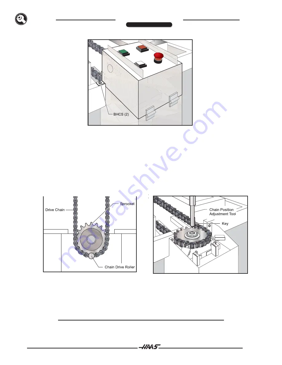
Figure  3.8  APC operator's panel cover.

17.

Ensure that the drive roller on the APC chain is centered under the control box, as shown in Figure
3.9.  If not, use the chain position adjustment tool to rotate it into this position.

To use this tool, place it into the center of the drive sprocket with the key in the sprocket's keyway (see Figure
3.10). Note that the tool only goes about 1/4" into the sprocket.  Push down and turn the tool with a wrench in
order to position the chain.

Important! Remember to remove the adjustment tool when finished.

Figure 3.9  Chain drive roller positioning.

Figure 3.10  Chain position adjustment tool placement.

18.

Insert two 1/2"-13 eyebolts into each pallet (see Figure 3.11). Attach straps or chains to the
eyebolts, and use a forklift or hoist to lift each of the pallets onto the APC.  Ensure that each pallet
is placed with it's drive leg pawl under the APC operator's panel, and that the APC rollers fit into
the grooves on the bottom of the pallets (see Figure 3.12).

NOTE:

Be careful not to set the pallets on top of the chain drive roller.  If necessary,
rotate the chain slightly using the chain position adjustment tool.

INSTALLATION

Summary of Contents for APC

Page 1: ...ng pallets and a special automatic door in the side of the VMC enclosure allows for loading and unloading of pallets The APC has its own operator s panel which includes CYCLE START FEED HOLD PALLET READY and EMERGENCY STOP buttons The APC can be programmed to load a pallet or change pallets by calling an M50 When a pallet change is programmed the VMC table moves to the right and adjacent to the em...

Page 2: ...BETWEEN PALLETS 1 2 1 27 DISTANCE BETWEEN PALLET AND DOOR 40 101 6 PALLET LENGTH APC DIMENSIONS APC WORK ENVELOPES OF TOOL HOLDER V GROOVE LOWEST POINT ON CAROUSEL 9 22 86 cm C L 0F TOOL HOLDER TOOL CHANGER COVER C L 21 69 55 cm TOOL CHANGE POSITION 26 66 cm MAX Z AXIS TRAVEL MILL TABLE AT HOME POSITION SIZE VF 3 48 x 18 121 92 cm x 45 72 cm TRAVEL VF 3 40 x 20 101 60 cm x 50 80 cm ENCLOSURE USEAB...

Page 3: ... ANUAL A u t o m a t i c A u t o m a t i c A u t o m a t i c A u t o m a t i c P a l l e t C h a n g e r P a l l e t C h a n g e r INTRODUCTION APC PALLET CLEARANCES A 1 1 4 D 3 B 1 3 8 E 1 1 2 C 6 1 4 F 4 1 2 The same for both VF 3 and VF 4 ...

Page 4: ...om receiver pallet clamped switch Apply a light coat of grease and work the grease into the plunger Do not over grease WARNING WARNING WARNING WARNING WARNING Excessive chip buildup will require more frequent chip cleanup Clean the two locating pins in the receiver base and the corresponding bushings in the pallets Apply a very light coat of general purpose grease to the pins and bushings if neede...

Page 5: ...en wrenches Included APC jumper Prior to installing your VMC make certain that there is enough floor space on the right hand side of the VMC to place the APC The APC will add approximately 52 1 2 58 1 2 for the VF 4 to the width of the VMC Ensure that all the air and power requirements for the VMC have been met GENERAL REQUIREMENTS Operating Temperature Range 41 F to 104 F 5 to 40 C Storage Temper...

Page 6: ...ts and install the socket set screw plugs with Loctite see Figure 3 1 Lift off the pallets and set them aside Remove the door air cylinder and the cable bundle from their storage positions in the APC pan 1 2 Remove pallet shipping bolts and install 1 2 13 plugs Use Loctite Visually check to verify that plugs do not extend into roller channels It is important to install the plugs to prevent chips f...

Page 7: ...he VMC with two SHCS each Insert the door air line into the fitting at the base of the air cylinder 6 POWER ON the VMC and ZERO RETURN all axes Verify that the VMC operates normally 7 In MDI mode command an M17 The table will unclamp raise and the automatic door will open The door and table will stay up Clean all shipping protectant from the rollers alignment pins and clamp bars NOTE M14 will move...

Page 8: ...C while the VF 4 uses the two holes farthest from the VMC Leveling Pad Leveling Screw APC Leg APC Brace 3 8 SHCS 4 VMC Base HHB 2 VF 4 Holes 2 VF 3 Holes 2 Figure 3 6 Installing the APC brace shown 11 In MDI mode command an M14 The table will move to the pallet 1 load position The front right corner of the VMC 12 Place the straightedge on top of the rollers of both the VMC receiver unclamped and t...

Page 9: ...t parallel the APC must be moved The APC can be moved slightly by tapping on the leveling pads with a hammer NOTE If the rollers are parallel but are not aligned the adjustments will be made later in the Fine Tuning section 14 In MDI mode command an M15 The table will move to the pallet 2 load position right rear corner of the VMC Repeat Steps 12 and 13 with the table in this position 15 Tighten d...

Page 10: ...e sprocket Push down and turn the tool with a wrench in order to position the chain Important Remember to remove the adjustment tool when finished Figure 3 9 Chain drive roller positioning Figure 3 10 Chain position adjustment tool placement 18 Insert two 1 2 13 eyebolts into each pallet see Figure 3 11 Attach straps or chains to the eyebolts and use a forklift or hoist to lift each of the pallets...

Page 11: ...fting eyebolt locations Figure 3 12 Pallet placement 19 Pull the pallets onto the friction blocks and against the hard stop see Figure 3 13 Rotate the chain slightly using the chain position adjustment tool to allow each drive leg detent to clear the chain drive roller Figure 3 13 View of APC base showing friction block and hard stop 20 Power OFF the VMC WARNING WARNING WARNING WARNING WARNING Thi...

Page 12: ... r Figure 3 14 APC air hose connection to VMC air lube cross fitting 23 Position the coolant tank as shown Coolant Tank Placement SIDE DOORS FOR EXPORT MACHINES Automatic Pallet Changer Pallet Changer 1 APC with Safety Doors For machines equipped with safety doors be sure that doors are closed properly The APC will not function if the doors are not secure INSTALLATION ...

Page 13: ...saligned in the Y axis causing the pallet to shift to one side during loading and unloading variable 122 can be modified The following settings can be modified to adjust the table location for loading and unloading of pallets 121 APC PAL 1 LOAD X Pallet 1 load X position 122 APC PAL 1 LOAD Y Pallet 1 load Y position 123 APC PAL 1 UNLOAD X Pallet 1 unload X position 124 APC PAL 1 UNLOAD Y Pallet 1 ...

Page 14: ...e value initially and may be adjusted separately later if either loading or unloading is not smooth If alignment appears to be incorrect in the Z axis height adjust it by turning the leveling screws until pallet loading and unloading is smooth 5 Push the pallet back onto the APC In MDI mode command an M15 to move the pallet to load position 2 Repeat Steps 3 and 4 above for pallet 2 The APC height ...

Page 15: ...ion by adjusting setting 121 for pallet 1 and setting 125 for pallet 2 Typically the load and unload positions will be the same for both pallets Nudge the pallet to align the pin and bushing then press CYCLE START The pallet should clamp fully down Repeat the X axis alignment process until the pin and bushing are aligned A perfectly aligned pallet will move straight up and down when clamping and u...

Page 16: ...llets and the second program runs a different part on each pallet The APC has its own operator s panel which includes CYCLE START FEED HOLD and EMERGENCY STOP buttons that perform the same functions as those on the VMC control panel This panel also includes a PALLET READY button which is used for APC functions Refer to figure 4 1 Figure 4 1 APC operator s control panel top view If the pallet ready...

Page 17: ...there is already a priority number for that pallet the Load Order numbers of the other pallets will be updated as necessary A pallet that is in the receiver will have an asterisk in the Load Order column The home position for each pallet is as follows Pallet 1 tp the right and closest to the control pendant Pallet 2 to the right and furthest fom the control pendant Pallet 3 to the left and furthes...

Page 18: ... Pressing F1 closes the menu without changing the status of any of the pallets Resetting a status item to USER is done by selecting an item from the menu and selecting F4 All status items can be reset at the same time with the ORIGIN key Changing the status of an individual pallet can be done from the PST or with the M49 command In the PST move the table cursor to the PALLET STATUS column for the ...

Page 19: ...ode generates alarm 909 if the current program is not listed in the Pallet Schedule Table It generates alarm 910 if the pallet that is currently loaded is not listed in the Pallet Schedule Table for the current program M49 Set Status of Pallet This M code sets that status of the pallet specified by the P code to the value specified by the Q code The possible Q codes are 0 Unscheduled 1 Scheduled 2...

Page 20: ...inch mm 149 APC PAL 3 UNLOAD Y This is the APC pallet 3 Y axis unload position It should be set at the time the Quad APC is installed Units are inch mm 150 APC PAL 4 LOAD X This is the APC pallet 4 X axis load position It should be set at the time the Quad APC is installed Units are inch mm 151 APC PAL 4 LOAD Y This is the APC pallet 4 Y axis load position It should be set at the time the Quad APC...

Page 21: ...M36 Flash Pallet Ready light wait until PALLET READY button pressed to continue M50 Perform pallet change after Pallet Ready button is pressed M96 Q27 Pxx This line will check to see if pallet 1 is on the machine If it is then it will jump to line xx If the pallet is not on the machine then it will continue to the next line Q27 checks to see if pallet 1 is on the machine See VF Series Operator s M...

Page 22: ...let Status The pallets will be processed in the order 3 4 and finally 2 column 2 Load Order with the program indicated in column 5 Program Number The Program Comment is captured from the program listed in column 5 Pallet Schedule Sample Table 1 Pallet Load Pallet Pallet Program Program Number Order Status Usage Number Comment 1 0 UNSCHEDULED 12 O06012 CUT SLOT 2 3 SCHEDULED 13 O05870 DRILLAND TAP ...

Page 23: ...le Table 4 Table Pallet Schedule Sample Table 4 Pallet Load Pallet Pallet Program Program Number Order Status Usage Number Comment 1 0 UNSCHEDULED 12 O06012 CUT SLOT 2 LOADED 14 O05870 DRILLAND TAP 3 0 COMPLETED 23 O04990 ROUGHAND FINISH TOG 4 0 LAST PALLET 9 O06012 CUT SLOT Description In the fourth loop the M50 will detect that no pallets are scheduled The beacon light will flash green and progr...

Page 24: ... for Pallet 4 for Pallet 4 Nxxxx Line number M99 Repeat program see VF Series Operator s Manual for a more detailed description of M99 Example 3 This is an alternate method to Example 2 that uses subroutine calls but does not jump if the pallet is unscheduled M36 P1 Flash NO PALLET SCHEDULED on display flash green beacon flash light on SCHEDULE PALLET button for pallet 1 until button is pushed or ...

Page 25: ...riable are generally read only Pallet priority 7501 7504 and pallet status 7601 7604 are read write during some conditions but read only for others For example both are read only while the pallet is loaded These variable are maintained in memory during power off VARIABLES USAGE 3028 Number of pallet loaded on receiver 7501 7504 Pallet priority 7601 7604 Pallet status 7701 7704 Part program numbers...

Page 26: ...UTOMATIC DOOR Used for machine installation only Clamp pallet Check Receiver Clamp switch If receiver not clamped within the amount of time set in parameter 316 generate alarm 633 Close automatic door Check Door Open switch If door not closed generate alarm 639 M36 HOLD UNTIL PALLET READY BUTTON IS PRESSED When PALLET READY button is pressed enable an M50 pallet change see below M50 PERFORM PALLET...

Page 27: ...ock trips the Chain Stop switch Clamp receiver Move table away from automatic door Return to Normal Operation Turn beeper off Disable chain drive Close automatic door NOTE The M50 pallet change must be successfully completed before normal VMC operation can continue If the M50 pallet change is interrupted software switches will not allow normal VMC operation Another M50 must be run to reset the swi...

Page 28: ...ero Return auto all axes Do not Zero a single axis Do not Jog or otherwise move the X and Y axes With power and air supply ON have an assistant manually actuate the solenoids on the lube panel to open the APC door and unclamp the receiver Constant pressure must be maintained on the actuators to provide a continuous air flow see Figure 4 Release the solenoid actuators Zero the axes NO YES There are...

Page 29: ...PC Pallet home switches and Pin Clear switches are under the control panel Figure 1 Pallet known locations Pallet 1 is on the receiver and engaging the Pallet Clamped switch Pallet must be clamped to trip this switch Pallet 2 is on the APC and engaging the Pallet Home Switch under the control panel Alignment pin Receiver Pallet Pallet Clamp Switch Alignment Pin Receiver Bushing Figure 2 Alignment ...

Page 30: ...t C h a n g e r Figure 3 With pallet 2 clamped on the receiver the trip block must be engaging the switch as shown Figure 4 Press and hold the solenoid actuation buttons small white buttons to keep air pressure flowing to unclamp the receiver and hold the door open If the buttons are released the door will close and the receiver will clamp TROUBLESHOOTING ...

Page 31: ...rear of mill and continuously press both white buttons in center of solenoid air valves while an assistant pulls the pallet off the receiver After correcting the condition run an M50 to continue machining 632 APC Unclamp Error The pallet did not unclamp in the amount of time allowed This can be caused by a bad air solenoid a blocked or kinked air line or a mechanical problem After correcting the c...

Page 32: ... pallets home or one pallet home and one on the receiver The chain position adjustment tool must be used to rotate the chain into position The pallets must be pushed into place by hand After correcting the condition run an M50 to continue machining 642 APC Incorrect Chain Location Chain not in position to load or unload pallets when necessary To correct this the mislocated pallet must be moved bac...

Page 33: ...m the APC to the receiver in the allowable time Pallet change sequence was halted because receiver switch was not activated Pallet is either unclamped or not on the receiver Ensure the pallet is correctly located on receiver against hard stop then run M18 to clamp the pallet After correcting the condition run an M50 to continue machining Alarm 919 APC Load Switch Missed Pal 2 Pallet 2 did not comp...

Page 34: ...IFICATIONS Weight 300 lbs Thickness 1 1 2 Bolt Holes 5 inch spacing 1 2 13 X 3 4 DP threads CAUTION Drilled holes in pallet should be less than 1 deep Figure 7 1 Pallet bolt hole pattern and spacing CAUTION For pallet loads over 250 lbs the load should be distributed evenly around the center of the pallet to avoid tipping the pallet during loading and unloading TECHNICAL REFERENCE ...

Reviews: