16
96-0012 rev G
June 2003
O
M
PERATOR’S
ANUAL
A u t o m a t i c
A u t o m a t i c
A u t o m a t i c
A u t o m a t i c
P a l l e t C h a n g e r
P a l l e t C h a n g e r
4.0 PROGRAMMING
4.1 P
ROGRAM
C
OMMANDS
The APC is controlled by a program in CNC memory. M codes are used in the parts program to control the
APC. The pallet change routine is run by using an M50 code in the parts program. In order for M50 to work the
APC load and unload coordinate must be set (settings 121 through 128). Make sure that the X coordinate safe
distance, setting 129, is set to -33.000.
The APC can be programmed to run one program on both pallets, or a different program on each pallet. The
"Sample Programs" section consists of two basic programs: the first sample program runs the same part on
both pallets, and the second program runs a different part on each pallet.
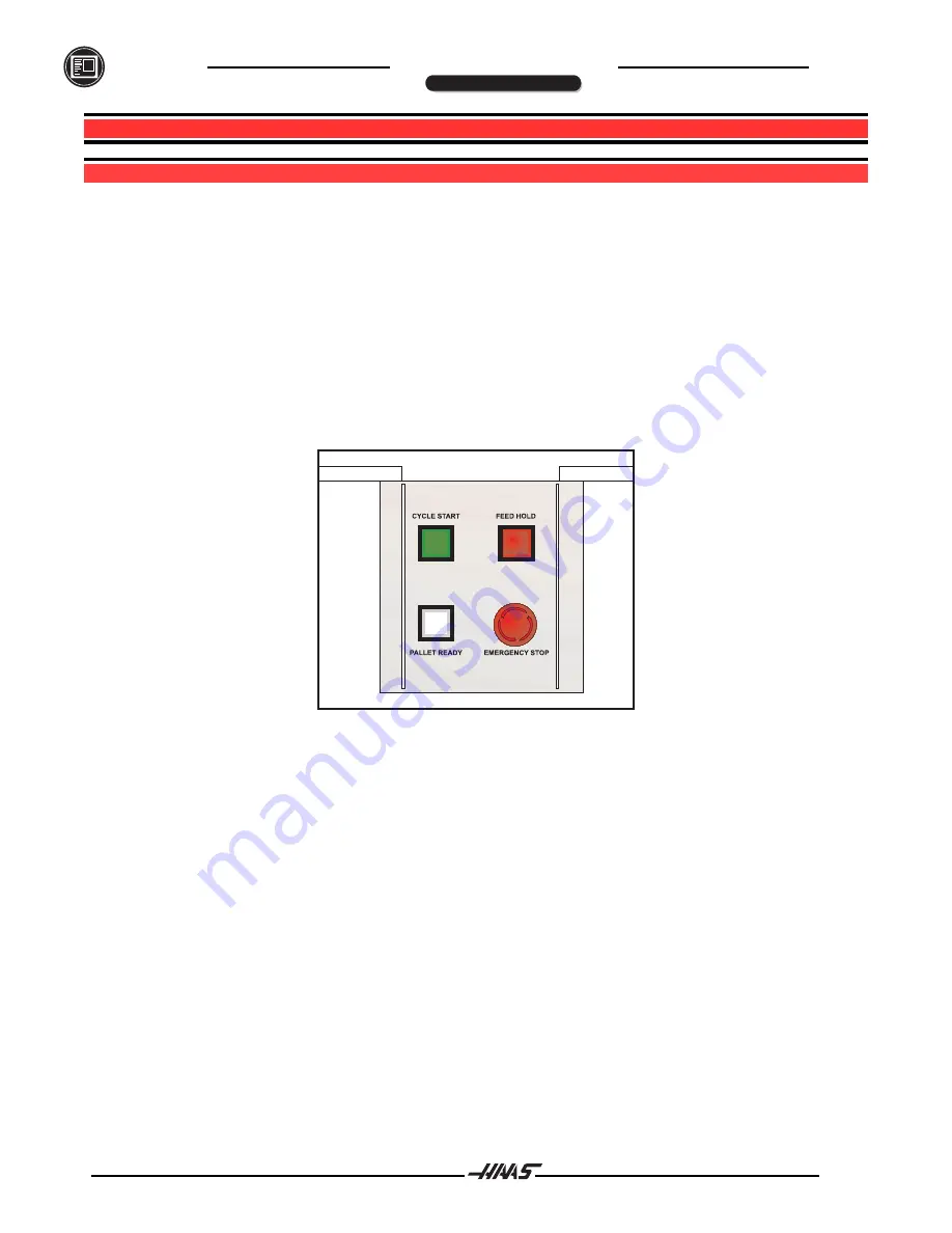
The APC has its own operator's panel, which includes CYCLE START, FEED HOLD, and EMERGENCY STOP
buttons that perform the same functions as those on the VMC control panel. This panel also includes a
PALLET READY button, which is used for APC functions. Refer to figure 4.1.
Figure 4.1 APC operator's control panel (top view).
If the pallet ready key has not been pressed, the APC will flash the "PALLET READY" light at the completion of
the user's part program, and wait until the PALLET READY button has been pressed before performing the
pallet change. This feature prevents a pallet change from occurring before the operator is ready. The PALLET
READY button can be pressed at any time and will be recognized when the next program is finished and a
pallet change is required.
Important!
If alignment adjustments are necessary during operation, refer to the "Installation" section and
modify the appropriate settings.
PROGRAMMING


