96-0012 rev G
9
June 2003
O
M
PERATOR’S
ANUAL
A u t o m a t i c
A u t o m a t i c
A u t o m a t i c
A u t o m a t i c
P a l l e t C h a n g e r
P a l l e t C h a n g e r
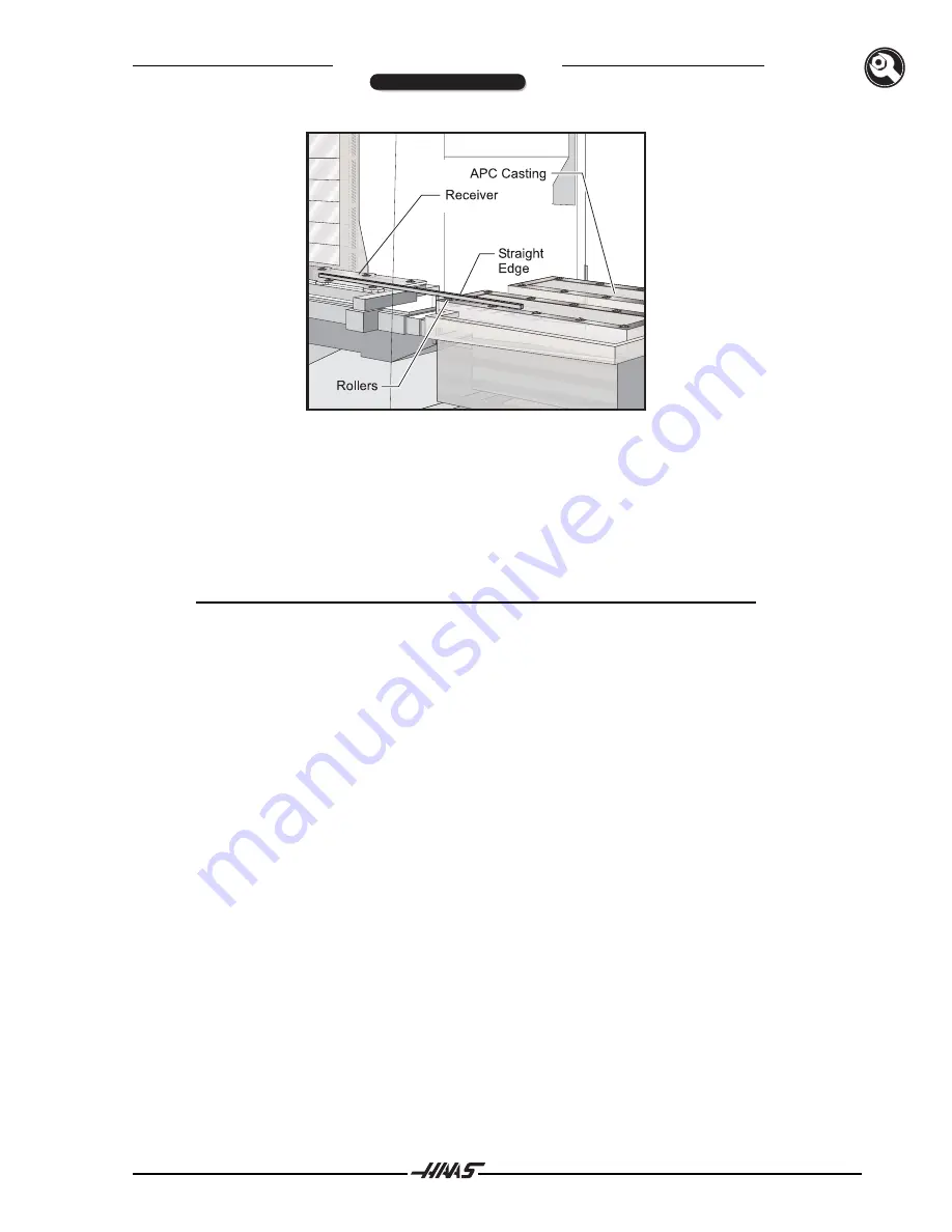
Figure 3.7 APC roller alignment setup.
13.
Place the straightedge against the side of the rollers on the VMC receiver and the APC, to ensure
that the rollers are aligned in the Y-axis. The straightedge must extend past at least two rollers on
both the APC and VMC to get an accurate reading.
If the rollers are not parallel, the APC must be moved.
The APC can be moved slightly by tapping on the
leveling pads with a hammer.
NOTE:
If the rollers are parallel, but are not aligned, the adjustments will be made later
in the "Fine Tuning" section.
14.
In MDI mode, command an M15. The table will move to the pallet #2 load position (right rear corner
of the VMC). Repeat Steps 12 and 13 with the table in this position.
15.
Tighten down the four 3/8 SHCS and two hex-head bolts (see Figure 3.6) on the APC brace
evenly
, so the APC is not pulled out of alignment. Recheck the level and all alignments.
Setting up the APC
16.
Open the hinged APC operator's panel cover by removing the two BHCS (see Figure 3.8).
INSTALLATION


