ES0755 rev A 1/11
19
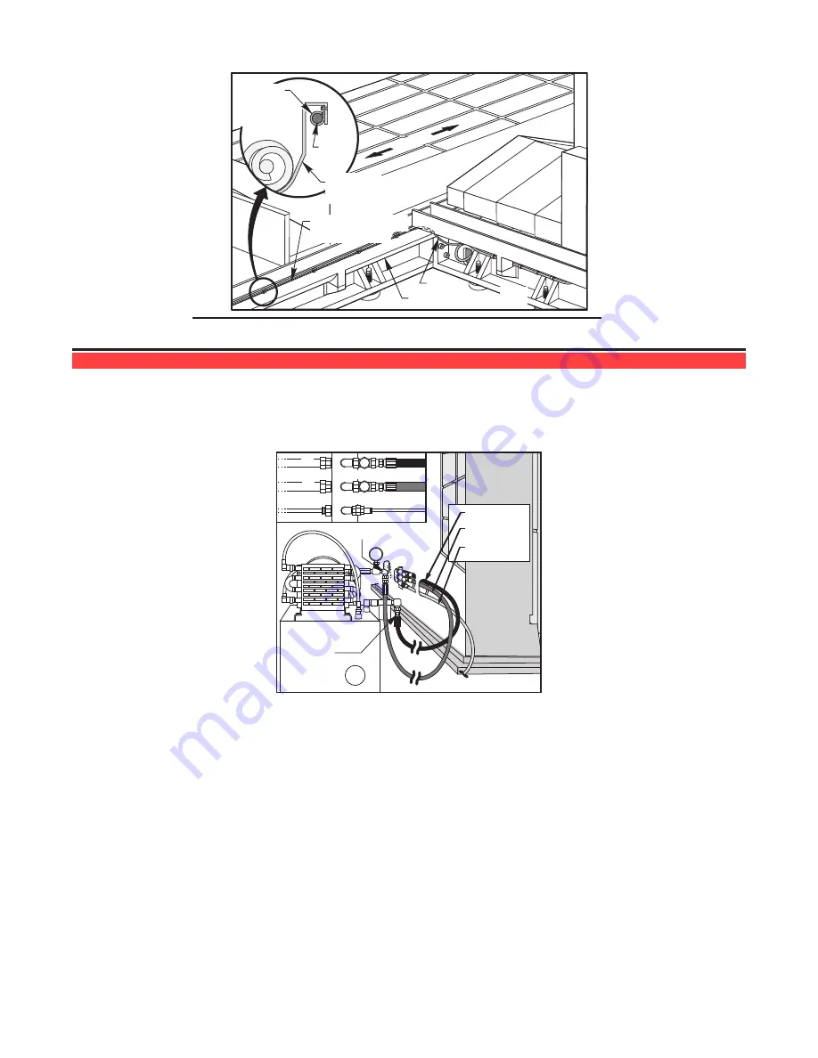
Cable
Support
Clamp
Cable
Cable
X-Axis
X-Axis Auger
Trough
Cable (To X-Axis
Auger Motor)
X-Axis Auger Trough
condition exists, please contact Haas factory service.
t
ool
c
hanGer
i
nstallation
/a
liGnment
Installing the Hydraulic Power Unit (HPU)
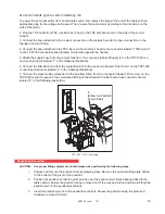
Before placing the Tool Changer, position the HPU behind the machine. This
must
be done before the tool
changer is installed, otherwise there may not be room to maneuver the HPU between the tool changer and
any obstacles. Once in position, install the hoses as shown.
High Pressure
Low
Pressure
High Press.
Low Press.
Air
Air
T
P
High Pressure
Low Pressure
Hydraulic Power Unit Information
Maximum Pressure: 1000 PSI
Hydraulic Fluid: DTE 25 (Do Not Mix)
Tool Changer Maximum system pressure: 700 PSI
Pressure Hose (52-0008): 1/2” JICF x 84” L
Maximum Flowrate@ 1800RPM: 10.5 GPM
Return Hose (52-0000): 1/2” JICF x 90” L
Reservoir Volume: 20 Gallons
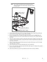
1. Check level of hydraulic fluid in reservoir by inspecting the sight gage located on the side of the reservoir. If
necessary, add hydraulic fluid (DTE 25) to the reservoir until the level reaches the top of the sight gage.
2. Connect pressure and return hoses from the hydraulic power unit (HPU) to the tool changer. The pressure
hose connects the pump outlet to the middle port on the tool changer manifold; the return hose connects the
bottom port on the tool changer manifold to the filter inlet on the hydraulic power unit. Note that if the HPU is
operated for the first time, skip to step 7 for initial adjustment of hydraulic system pressure and flow settings.
3. Connect the supply airline (1/4” plastic hose) from the machine’s air-lube panel to the upper fitting on the
tool changer manifold.


