ES0755 rev A 1/11
24
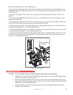
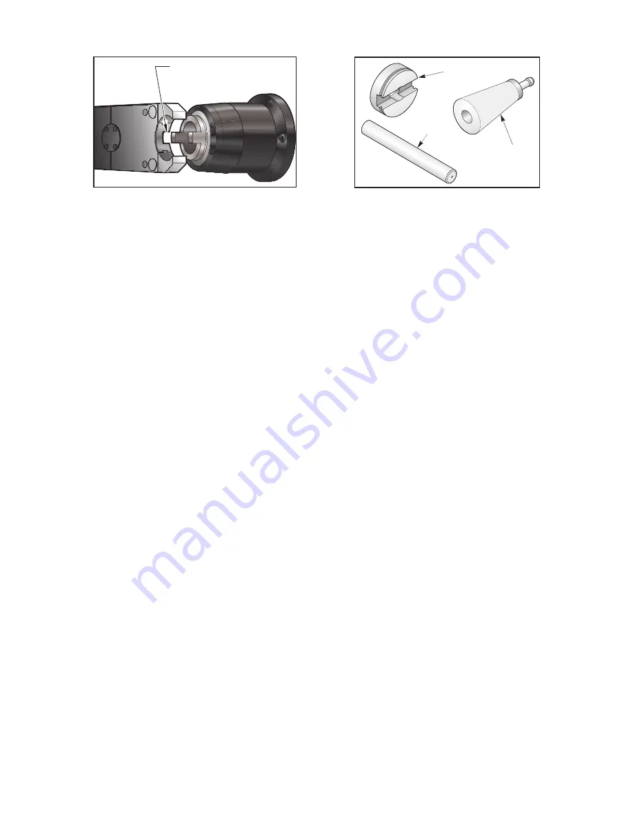
Key Tab
Jig
Dowel Pin
Taper
Key Tab Alignment
Alignment Jig
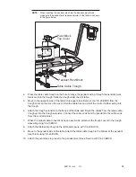
9. Press
PAGE DOWN
until the tool changer is back to the stow position. Using the alignment jig dowel pin,
push the top half of the jig into the double arm fingers. Insure that it is inserted properly and that the flat side
faces the spindle. Press
TOOL RELEASE
and install the taper into the spindle.
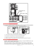
10. Press
HOME
and swing the tool changer towards the spindle. Insure it is in hydraulic lock.
11. Press
>
and slide the double arm all the way to the spindle until it locks. Adjust the three transition (slide)
bolts until the jig halves are aligned by sight. Insert the dowel pin, if it goes all the way through, the alignment
is complete. Tighten the lock nuts on the slide and leveling bolts. If the dowel pin does not go through all the
way, continue with fine adjustments using the slide and leveling bolts to adjust the tool changer left, right and
perpendicular to the spindle.
12. Press
ALARM MESGS
, type “DEBUG” and press
ENTER
. Press
POSIT
, Press
HANDLE JOG
and
jog the Z axis until the air gap between the jig halves is 1.5mm (.059”) in all directions. Enter the value into
parameter number 64 (omit the decimal point).
13. Handle jog the Y-axis moving the spindle up or down to align jig halves. Enter the value into parameter
number 211 (omit the decimal point).
14. Rotate the arm and switch the alignment jig to the other side. Adjust as necessary so that the alignment
pin inserts fully. Repeat steps 11-13 until the dowel pin inserts fully in both sides of the arm.
15. Tighten all locking nuts. Home tool changer and magazine. Exit from tool changer restore mode by
pressing jog handle mode.
Setting the Tool Change Position Parameters
Without moving the tool changer arm, spindle or column from the position achieved in Step 15:
1. Go to the
SETTINGS/GRAPH
display screen by pressing the <
SETNG/GRAPH
> button.
2. Go to Setting
#7
,
PARAMETER LOCK
and change it to
OFF
by pressing <
>
> (right arrow) button and then
press the <
WRITE/ENTER
> button to save it in memory.
3. Go to the
ALARMS
display screen by pressing the <
ALARM/MESGS
> button. Type in
DEBUG
from the
keypad and press the <
WRITE/ENTER>
button.
4. Move to the
POSITION
display screen by pressing the <
POSIT
> button. Press the <
PAGE UP
> button to
move to the
POS-RAW DAT
screen.
5. Record the values shown in the
ACTUAL
column for the position of the Y and Z-axes.
6. Go back to the
ALARMS
screen, type in
DEBUG
and press the <
WRITE/ENTER>
button to exit the
DEBUG
mode.
7. Press the <
E-STOP
> button to allow parameters to be changed.
8. Go to the
PARAMETERS
display screen by pressing the <
PARAM/DGNOS
> button. Go to Parameter
#211, Y Tool Change Offset,
on the
“Y PARAM B”
screen. Enter the number (with the correct sign) recorded
from the
POS-RAW DAT
screen for the Y-axis and press the
WRITE/ENTER
button.


