ES0755 rev A 1/11
26
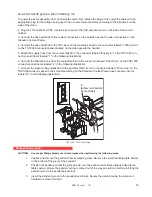
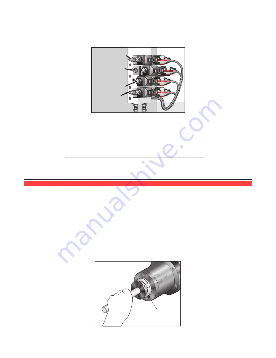
The carousel speed and the arm’s pull-in/push-out speed are directly controlled by the flow rate of the hydrau
-
lic pump. Thus, increasing the flow rate will increase the speed of these functions and conversely decreas
-
ing the flow rate will decrease their speed. The speed of the other six functions are controlled by flow control
valves located on the tool changer’s valve manifold.
Arm Slide Valve
(Mag)-(Spindle)
Arm Slide Valve
(Left)-(Right)
Arm Pull-In/
Push-Out Valve
(In)-(Out)
Arm Rotate Valve
(CW)-(CCW)
Hydraulic Pump Pressure and Flowrate Adjustment Screws
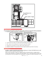
2. If it is necessary to adjust the speed of a function controlled by a valve perform the following:
a. Locate the valve that controls the function.
b. Loosen the locknut on the appropriate flow control valve.
c. Turn the flow control adjustment screw counterclockwise to increase flow (increase speed), or
turn the adjusting screw clockwise to decrease flow (speed).
NOTE:
Make adjustments in ¼ turn increments as small adjustments can
cause large changes in speed.
d, After completing the adjustment, tighten the adjustment screw locknut.
t
ool
c
hanGer
a
liGnment
v
erification
TC alignment must be verified before loading any tools. Any adjustment or change to the machine level
will affect TC alignment. Incorrect TC alignment can result in dropped tools, damaged waycovers, cambox
damage, excessive wear, and damage to the TC double-arm.
Warning
Verify tool changer alignment before operating the mill.
As a safety precaution the Service technician must ensure the tool changer is aligned properly to the spindle.
The installation and leveling of a new machine affects tool changer alignment. Use the following instructions
to verify alignment. Do not load any tools into the tool changer or spindle until alignment is complete.
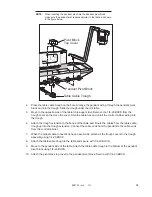
Tool Required: Split Tool P/N
T-2088 for 50 taper, BT tooling
T-2089 for 50 taper, CT tooling
Pinch Point
\
Split Tool


