ES0755 rev A 1/11
29
c
oolant
s
ystem
i
nstallation
c
oolant
s
eParator
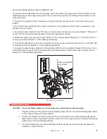
The coolant separator is mounted in its shipping position. Remove the two screws and remount the coolant
separator in the lower mounting location. Do this for
both of the coolant separators.
Cable
Trough
Coolant Separator
Operating Position
Coolant Pump,
coolant level sensor
and TSC cables
Coolant Trough
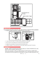
Route the coolant tank and TSC (optional) cables through the coolant trough. If necessary remove the trough
(2 screws) to ensure that the cables are properly routed.
c
oolant
t
ank
I
nstallation
1. Position the coolant tank.
Electrical Sub-Panel
NOTE:
It is important that the coolant tank is in place before leveling the
machine to ensure there is adequate clearance (height) between
the bottom of the auger trough and the tank.
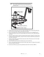
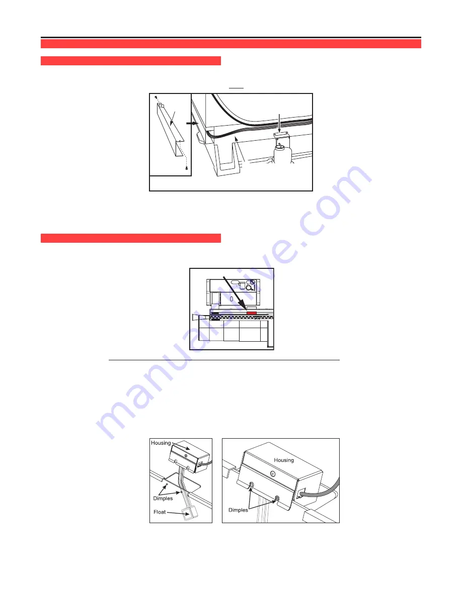
2. The Coolant Level Float Assembly is shipped in a separate box. It consists of a housing, float and cable.
Install the Coolant Level Float Assembly by lowering the float through the tank lid. Line up the slots in the
housing with the dimples on the side of the tank and press down so the float assembly clips onto the tank.
95-Gallon coolant tank
- The float can be mounted on either the edge of the coolant tank or the center.
3. Insert a plastic push wire mount into the hole in the tank lid, then route the cable to the coolant pump(s). Tie
wrap the coolant float cable to other cables, when available, when routing from the coolant tank (see figure).


