ES0755 rev A 1/11
33
240-230V 50/60HZ @ 20A or 480V 50/60HZ @ 10A
To power the pump assembly from an alternate source, first replace the plug at the end of the cable with an
appropriate plug for the voltage being used. Then, rewire the pump motor according to the directions on the
side of the motor.
2. Plug the TSC cable from TSC junction box (J-box) to the TSC amphenol port on the side of the control
cabinet.
3. Connect the hose attached to the coolant connection on the spindle head to the hose connection on the
Standard Coolant Pump.
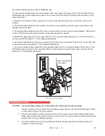
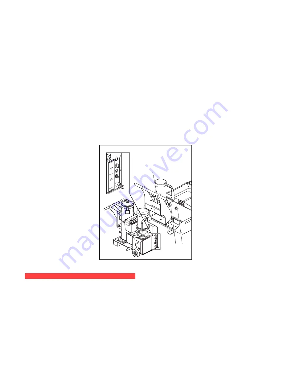
4. Connect the hose attached to the TSC input on the machine’s head to the connector labeled “1000 psi Out”
on the TSC1000 connector panel (located on the side opposite the handle).
5. Attach the supply hose from the coolant tank lid to the connector labeled “Supply In” on the TSC1000 con-
nector panel (items labeled “1” in the following illustration).
6. Connect the filter drain line from the coolant tank lid to the connector labeled “Filter Drain” on the TSC1000
connector panel (items labeled “2” in the following illustration).
7. Connect the plastic tubing (ships tied to the Auxiliary Filter) from the connector labeled “Prime Line” on the
TSC1000 connector panel to the small elbow fitting on the Standard Coolant Pump hose connector (items
labeled “3” in the following illustration).
1
1
2
2
3
3
(Elbow on Standard
Pump Outlet)
TSC1000 / HPC1000 Setup
P
endant
i
nstallation
CAUTION: Use proper lifting equipment and techniques when performing the following steps.
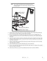
1. Unpack and remove the pendant from its shipping crate. Remove the small retaining plate bolted
to the bottom of the pivot of the pendant.
2. Position the pendant so that the pivot point is near the pendant pivot block already bolted to the
table casting. Ensure the pendant wiring is moved out of the way and will not interfere in fitting the
pendant pivot to the pendant pivot block.
3. Insert the pendant pivot into the pendant pivot block. Secure the pendant using the plate and
hardware removed in Step 1.


