ES0755 rev A 1/11
4
mating surfaces.
2. Prepare the column base for mating
• Stone and clean thoroughly the mating flange surface. This is an extremely important step
that must be well and properly done before the bases are moved into position with respect
to each other.
(Failure to properly prepare the surfaces and preserve their cleanliness
may require separation of the main components for corrective action).
• Check the thread of each hole in the column base, ensure there is no damage.
• Ensure the air/electrical/oil lines and connectors are safely away from the mating surfaces.
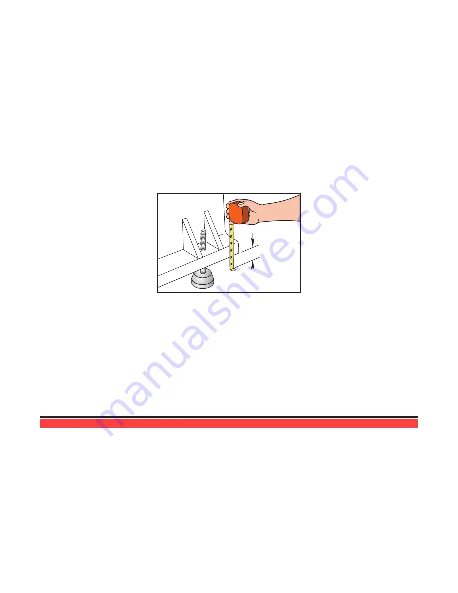
3. Place the column base assembly in position. Rough level by measuring from the floor to the bot
-
tom of the base (very close to 2 inches). Each of the leveling screws and pads should be in place
at this time and it is advisable to take the measurement at each leveling screw location for best
results. This will ensure that the final leveling procedure will go more quickly and that the coolant
tank will properly fit beneath the coolant discharge. Loosely screw the jam nuts onto the leveling
screws.
1
2
3
4
5
6
2" min.
4. Place the table base assembly in position. When placing the table base in position with respect
to the column base, it is important that the two mating flanges be as parallel as possible (verti
-
cally and horizontally). Be certain that each of the nineteen screws are actually engaged in the
threads, and that when the column base is in place and the mating surfaces are in contact that
each screw is free to rotate. Rough level by measuring from the floor to the bottom of the base
(very close to 2 inches). Each of the leveling screws and pads should be in place at this time
and it is advisable to take the measurement at each leveling screw location for best results. This
will ensure that the final leveling procedure will go more quickly. After rough leveling, fully tighten
the connecting screws to be sure the mating surfaces are in full contact, and then loosen them
all approximately 3 full turns. Be certain that the connecting screws are still free to rotate (do not
leave the connecting bolts tight at this time because the machine still must be final leveled and
squared).
3.1 i
nitial
s
etuP
WARNING!
At this point, there should be NO electrical connection to the machine. The electrical panel should
be closed and the three latches on the door should be secured at all times except during installation
and service. At those times, only qualified electricians should have access to the panel. When the
main switch is on, there is high voltage throughout the electrical panel (including the circuit boards
and logic circuits) and some components operate at high temperatures. Therefore, you must exer-
cise extreme caution when you are working in the panel.
1. Set the main switch at the upper right of the electrical panel on the back of the machine to OFF.
2. Unlock the cabinet with the key and open the door.


