1-15-96
96-8100
127
TABLE OF CONTENTS
ELECTRICAL SERVICE
VF-S
ERIES
S E R V I C E M A N U A L
HAAS
AUTOMATION, INC.
F1
FUSES
F2
FUSES
3.3 SERVO DRIVER & SDIST FUSES
1. Turn the main switch (upper right of electrical cabinet) to the off position.
2. Using a large flat tip screwdriver, loosen the three screws on the cabinet door and then open the door enough to safely
work on the electrical panel. Wait until at least the red CHARGE light on the servo drive assembly goes out before
beginning any work inside the electrical cabinet.
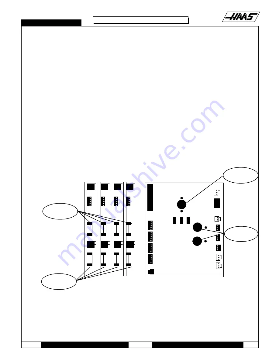
3. On the SERVO DRIVE ASSEMBLY, there are three fuses on the SDIST panel, and three individual fuses on each of the
SERVO DRIVE boards (See Fig. 3-4; the F3 fuses are not shown).
4. On the SDIST panel, use a flat tip screwdriver to turn the fuse(s) counterclockwise to remove. Replace the blown fuse(s)
with ones having the same type and rating (FU1, FU2: ½ amp, type AGC, 250V; FU3: 5 amp, type ABC, 250V).
5. On each of the SERVO DRIVER boards, the fuses (F1, F2, F3) may be replaced by simply pulling out the fuses by hand
and replacing with fuses of the same type and rating (F1, F2: 20 amp, type ABC, 250V; F3: 10 amp, type ABC, 250V).
P8
P3
P2
X
AXIS
Y
AXIS
Z
AXIS
A
AXIS
TB2
FU3
LE1
R2 R15 R11
FU2
FU1
P1
P2
P3
P4
P7
P8
TB1
P11
P9
P12
P13
P10
P5
F1
F2
Fig 3-4 Servo Drive Assembly; fuse locations
F3
FUSE
F1 & F2
FUSE
Summary of Contents for VF-SERIES
Page 180: ...1 15 96 96 8100 177 TABLEOFCONTENTS TECHNICAL REFERENCE SERVICE M A N U A L VF SERIES ...
Page 235: ...96 8100 1 15 96 232 VF SERIES S E R V I C E M A N U A L ASSEMBLY DRAWINGS VF 1 COLUMN ...
Page 237: ...96 8100 1 15 96 234 VF SERIES S E R V I C E M A N U A L ASSEMBLY DRAWINGS VF 1 LEADSCREW ...
Page 239: ...96 8100 1 15 96 236 VF SERIES S E R V I C E M A N U A L ASSEMBLY DRAWINGS VF 3 COLUMN ...
Page 241: ...96 8100 1 15 96 238 VF SERIES S E R V I C E M A N U A L ASSEMBLY DRAWINGS VF 3 LEADSCREW ...
Page 245: ...96 8100 1 15 96 242 VF SERIES S E R V I C E M A N U A L ASSEMBLY DRAWINGS 3 4 2 1 ...


