1-15-96
96-8100
183
TABLE OF CONTENTS
PARAMETERS
S E R V I C E M A N U A L
VF-S
ERIES
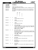
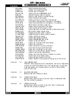
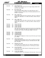
REV CRANK
Reverses direction of jog handle.
DISABLE T.C.
Disables tool changer operations.
DISABLE G.B.
Disables gear box functions.
POF AT E-STP
Causes power off at EMERGENCY STOP.
RIGID TAP
Indicates hardware option for rigid tap.
REV SPIN ENC
Reverses sense direction of spindle encoder.
REPT RIG TAP
Selects repeatable rigid tapping.
EX ST MD CHG
Selects exact stop in moves when mode changes.
SAFETY CIRC.
This enables safety hardware, if machine is so equipped.
SP DR LIN AC
Selects linear deceleration for rigid tapping. 0 is quadratic.
PH LOSS DET
When enabled, will detect a phase loss.
COOLANT SPGT
Enables coolant spigot control and display.
OVER T IS NC
Selects control over temp sensor as N.C.
SKIP OVERSHT
Causes Skip (G31) to act like Fanuc and overshoot sense point.
NONINV SP ST
Non-inverted spindle stopped status.
SP LOAD MONI
Spindle load monitor option is enabled.
SP TEMP MONI
Spindle temperature monitor option is enabled.
ENA ROT & SC
Enables rotation and scaling.
ENABLE DNC
Enables DNC selection from MDI.
ENABLE BGEDT
Enables BACKGROUND EDIT mode.
ENA GRND FLT
Enables ground fault detector.
KEYBD SHIFT
Enables use of keyboard with shift functions.
ENABLE MACRO
Enables macro functions.
SPIN COOLANT
Enables spindle low oil pressure detection.
INVERT SKIP
Invert sense of skip to active low=closed.
HANDLE CURSR
Enable use of jog handle to move cursor.
NEG WORK OFS
Selects use of work offsets in negative direction.
ENA CONVERSE
Enables conversational programming.
OILER ON/OFF
Enables oiler power when servos or spindle is in motion.
NC OVER VOLT
Inverts sense of over voltage signal.
ALT CHAR SET
Enables alternate character set on CRT.
DOOR STOP SP
Enables functions to stop spindle and manual ops at door switch.
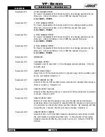
Parameter
58
LEAD COMPENS SHIFT
Shift factor when applying lead screw compensation. Lead screw compensation
is based on a table of 256 offsets; each +\-127 encoder steps. A single entry
in the table applies over a distance equal to two raised to this parameter
power encoder steps.
Parameter
59
MAX FEED RATE (INCH)
Maximum feed rate in inches per minute.
Parameter
60
TURRET START DELAY
Maximum delay allowed in start of tool turret. Units are milliseconds. After
this time, an alarm is generated.
Parameter
61
TURRET STOP DELAY
Maximum delay allowed in motion of tool turret. Units are milliseconds.
After this time, an alarm is generated.
Summary of Contents for VF-SERIES
Page 180: ...1 15 96 96 8100 177 TABLEOFCONTENTS TECHNICAL REFERENCE SERVICE M A N U A L VF SERIES ...
Page 235: ...96 8100 1 15 96 232 VF SERIES S E R V I C E M A N U A L ASSEMBLY DRAWINGS VF 1 COLUMN ...
Page 237: ...96 8100 1 15 96 234 VF SERIES S E R V I C E M A N U A L ASSEMBLY DRAWINGS VF 1 LEADSCREW ...
Page 239: ...96 8100 1 15 96 236 VF SERIES S E R V I C E M A N U A L ASSEMBLY DRAWINGS VF 3 COLUMN ...
Page 241: ...96 8100 1 15 96 238 VF SERIES S E R V I C E M A N U A L ASSEMBLY DRAWINGS VF 3 LEADSCREW ...
Page 245: ...96 8100 1 15 96 242 VF SERIES S E R V I C E M A N U A L ASSEMBLY DRAWINGS 3 4 2 1 ...

