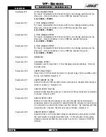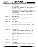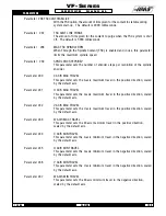
96-8100
1-15-96
186
PARAMETERS
S E R V I C E M A N U A L
VF-S
ERIES
Parameter
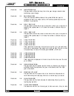
100
G MACRO CALL O9019 same as 91
Parameter
101
IN POSITION LIMIT X
How close motor must be to endpoint before any move is considered complete
when not in exact stop (G09 or G61). Units are encoder steps.
Parameter
102
IN POSITION LIMIT Y
Same definition as Parameter 101.
Parameter
103
IN POSITION LIMIT Z
Same definition as Parameter 101.
Parameter
104
IN POSITION LIMIT A
Same definition as Parameter 101.
Parameter
105
X MAX CURRENT
Fuse level in % of max power to motor. Applies only when motor is stopped.
Parameter
106
Y MAX CURRENT
Same definition as Parameter 105.
Parameter
107
Z MAX CURRENT
Same definition as Parameter 105.
Parameter
108
A MAX CURRENT
Same definition as Parameter 105.
Parameter
109
D*D GAIN FOR X
Second derivative gain in servo loop.
Parameter
110
D*D GAIN FOR Y
Second derivative gain in servo loop.
Parameter
111
D*D GAIN FOR Z
Second derivative gain in servo loop.
Parameter
112
D*D GAIN FOR A
Second derivative gain in servo loop.
Parameter
113
X ACC/DEC T CONST
Exponential acceleration time constant. Units are 1/10000 seconds. This pa
rameter provides for a constant ratio between profiling lag and servo velocity. It
is also the ratio between velocity and acceleration. In conjunction with Param
eter 7, it defines the speed above which exponential accel/decel is not provided.
Thus if Parameter 7 is 1200000 steps/sec/sec and this parameter is 750 (0.075
seconds); the maximum velocity for accurate interpolation should be:
1200000 x 0.075 = 90000 steps/second
For a 2000 line encoder and 6 mm screw, this would be 60 x 90000 / 33867 =
159 inches min
Summary of Contents for VF-SERIES
Page 180: ...1 15 96 96 8100 177 TABLEOFCONTENTS TECHNICAL REFERENCE SERVICE M A N U A L VF SERIES ...
Page 235: ...96 8100 1 15 96 232 VF SERIES S E R V I C E M A N U A L ASSEMBLY DRAWINGS VF 1 COLUMN ...
Page 237: ...96 8100 1 15 96 234 VF SERIES S E R V I C E M A N U A L ASSEMBLY DRAWINGS VF 1 LEADSCREW ...
Page 239: ...96 8100 1 15 96 236 VF SERIES S E R V I C E M A N U A L ASSEMBLY DRAWINGS VF 3 COLUMN ...
Page 241: ...96 8100 1 15 96 238 VF SERIES S E R V I C E M A N U A L ASSEMBLY DRAWINGS VF 3 LEADSCREW ...
Page 245: ...96 8100 1 15 96 242 VF SERIES S E R V I C E M A N U A L ASSEMBLY DRAWINGS 3 4 2 1 ...


