1-15-96
96-8100
195
TABLE OF CONTENTS
PARAMETERS
S E R V I C E M A N U A L
VF-S
ERIES
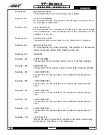
Parameter 236 TSC CLNT STABILIZE
With the TSC option, the amount of time given for the coolant to stabilize during
system start-up. The default is 4000 milliseconds.
Parameter 237
TSC CLNT LINE PURGE
The amount of time given for the coolant to purge when the TSC system is shut
off. The default is 5000 milliseconds.
Parameter 238
MAX TSC SPINDLE RPM
When Through the Spindle Coolant (TSC) is enabled and in use, this parameter
limits the maximum spindle speed.
Parameter 239
SPNDL ENC STEPS/REV
This parameter sets the number of encoder steps per revolution of the spindle
encoder.
Parameter 240
C AXIS MAX TRAVEL
This parameter sets the C-axis maximum travel in the positive direction, scaled
by the default axis.
Parameter 241
U AXIS MAX TRAVEL
This parameter sets the U-axis maximum travel in the positive direction, scaled
by the default axis.
Parameter 242
V AXIS MAX TRAVEL
This parameter sets the V-axis maximum travel in the positive direction, scaled
by the default axis.
Parameter 243
W AXIS MAX TRAVEL
This parameter sets the W-axis maximum travel in the positive direction,
scaled by the default axis.
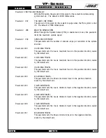
Parameter 244
C AXIS MIN TRAVEL
This parameter sets the C-axis minimum travel in the negative direction, scaled
by the default axis.
Parameter 245
U AXIS MIN TRAVEL
This parameter sets the U-axis minimum travel in the negative direction, scaled
by the default axis.
Parameter 246
V AXIS MIN TRAVEL
This parameter sets the V-axis minimum travel in the negative direction, scaled
by the default axis.
Parameter 247
W AXIS MIN TRAVEL
This parameter sets the W-axis minimum travel in the negative direction,
scaled by the default axis.
Summary of Contents for VF-SERIES
Page 180: ...1 15 96 96 8100 177 TABLEOFCONTENTS TECHNICAL REFERENCE SERVICE M A N U A L VF SERIES ...
Page 235: ...96 8100 1 15 96 232 VF SERIES S E R V I C E M A N U A L ASSEMBLY DRAWINGS VF 1 COLUMN ...
Page 237: ...96 8100 1 15 96 234 VF SERIES S E R V I C E M A N U A L ASSEMBLY DRAWINGS VF 1 LEADSCREW ...
Page 239: ...96 8100 1 15 96 236 VF SERIES S E R V I C E M A N U A L ASSEMBLY DRAWINGS VF 3 COLUMN ...
Page 241: ...96 8100 1 15 96 238 VF SERIES S E R V I C E M A N U A L ASSEMBLY DRAWINGS VF 3 LEADSCREW ...
Page 245: ...96 8100 1 15 96 242 VF SERIES S E R V I C E M A N U A L ASSEMBLY DRAWINGS 3 4 2 1 ...

