96-8100
1-15-96
196
PARAMETERS
S E R V I C E M A N U A L
VF-S
ERIES
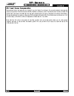
20.1 Lead Screw Compensation
Separate lead screw compensation is provided for each of the
X
,
Y
, and
Z
axes. The operator-entered compensation
values are spaced at 0.5 inch intervals within the machine coordinate system. The compensation values are entered in
inches with a resolution of 0.0001 inch. The operator entered values are used to interpolate into a table of 256 entries.
The spacing between two entries in the table of 256 is defined by Parameter 58. The entered values are limited to +/-127
encoder steps; so the limit in inches is dependent on Parameters 5, 19, and 33.
Note that the first entry corresponds to machine position zero and subsequent entries are for increasingly
negative positions in the machine coordinate system. The user should not ever need to adjust the lead screw
compensation tables.
Summary of Contents for VF-SERIES
Page 180: ...1 15 96 96 8100 177 TABLEOFCONTENTS TECHNICAL REFERENCE SERVICE M A N U A L VF SERIES ...
Page 235: ...96 8100 1 15 96 232 VF SERIES S E R V I C E M A N U A L ASSEMBLY DRAWINGS VF 1 COLUMN ...
Page 237: ...96 8100 1 15 96 234 VF SERIES S E R V I C E M A N U A L ASSEMBLY DRAWINGS VF 1 LEADSCREW ...
Page 239: ...96 8100 1 15 96 236 VF SERIES S E R V I C E M A N U A L ASSEMBLY DRAWINGS VF 3 COLUMN ...
Page 241: ...96 8100 1 15 96 238 VF SERIES S E R V I C E M A N U A L ASSEMBLY DRAWINGS VF 3 LEADSCREW ...
Page 245: ...96 8100 1 15 96 242 VF SERIES S E R V I C E M A N U A L ASSEMBLY DRAWINGS 3 4 2 1 ...


