96-8100
1-15-96
28
ALARMS
HAAS
AUTOMATION, INC.
S E R V I C E M A N U A L
VF-S
ERIES
155
Z-axis Z
same as 153.
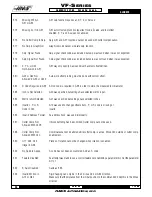
Ch Missing
156
A-axis Z
same as 153.
Ch Missing
157
Motor Interface
Internal circuit board problem. The MOTIF PCB in the processor stack is
PCB Failure
tested at power-on. Call your dealer.
158
Video/Keyboard
Internal circuit board problem. The VIDEO PCB in the processor stack is
PCB Failure
tested at power-on. This could also be caused by a short in the front panel membrane keypad.
Call your dealer.
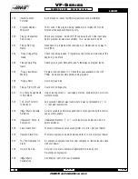
159
Keyboard Failure
Keyboard shorted or button pressed at power on. A power-on test of the membrane keypad
has found a shorted button. It can also be caused by a short in the cable from the main cabinet
or by holding a switch down during power-on.
160
Low Voltage
The line voltage to control is too low. This alarm occurs when the AC line voltage drops below
190 when wired for 230 volts or drops below 165 when wired for 208 volts.
161
X-axis Over Current
Current in
X
servo motor beyond limit. Possibly caused by a stalled or
or Drive Fault
overloaded motor. The servos are turned off. This can be caused by running a short distance
into a mechanical stop. It can also be caused by a short in the motor or a short of one motor
lead to ground.
162
Y-axis Over Current
same as 161.
or Drive Fault
163
Z-axis Over Current
same as 161.
or Drive Fault
164
A-axis Over Current
same as 161.
or Drive Fault
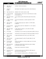
165
X Zero Ret
This alarm will occur if the home/limit switches move or are misadjusted.
Margin Too Small
This alarm indicates that the zero return position may not be consistent from one zero return to
the next. The encoder
Z
channel signal must occur between 1/8 and 7/8 revolution of where
the home switch releases. This will not turn the servos off but will stop the zero return opera
tion.
166
Y Zero Ret
Same as 165.
Margin Too Small
167
Z Zero Ret
Same as 165.
Margin Too Small
168
A Zero Ret
Not normally enabled for A-axis.
Margin Too Small
169
Spindle Direction
Problem with rigid tapping hardware. The spindle started turning in the
Fault
wrong direction.
Summary of Contents for VF-SERIES
Page 180: ...1 15 96 96 8100 177 TABLEOFCONTENTS TECHNICAL REFERENCE SERVICE M A N U A L VF SERIES ...
Page 235: ...96 8100 1 15 96 232 VF SERIES S E R V I C E M A N U A L ASSEMBLY DRAWINGS VF 1 COLUMN ...
Page 237: ...96 8100 1 15 96 234 VF SERIES S E R V I C E M A N U A L ASSEMBLY DRAWINGS VF 1 LEADSCREW ...
Page 239: ...96 8100 1 15 96 236 VF SERIES S E R V I C E M A N U A L ASSEMBLY DRAWINGS VF 3 COLUMN ...
Page 241: ...96 8100 1 15 96 238 VF SERIES S E R V I C E M A N U A L ASSEMBLY DRAWINGS VF 3 LEADSCREW ...
Page 245: ...96 8100 1 15 96 242 VF SERIES S E R V I C E M A N U A L ASSEMBLY DRAWINGS 3 4 2 1 ...


