96-8100
1-15-96
52
MECHANICAL SERVICE
HAAS
AUTOMATION, INC.
S E R V I C E M A N U A L
VF-S
ERIES
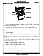
Fig. 4-1 Position wood block under spindle.
9. At the panel, go to the JOG mode and choose Z-axis. Slowly jog in the negative (-) direction until the spindle rests
on the block, then remove the screws that were previously loosened (step 7).
10. Jog Z-axis in the positive (+) direction until spindle is half way out of the head casting.
11. Grasp spindle with one hand and continue to jog in Z in the positive (+) direction until it is completely free of the
casting.
4.2 SPINDLE CARTRIDGE INSTALLATION
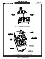
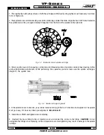
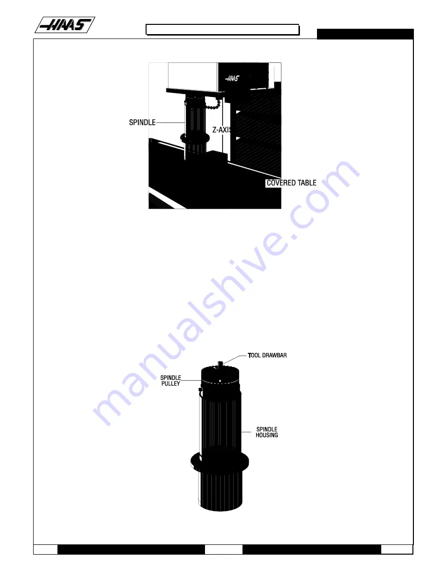
Fig. 4-2 Spindle cartridge.
Summary of Contents for VF-SERIES
Page 180: ...1 15 96 96 8100 177 TABLEOFCONTENTS TECHNICAL REFERENCE SERVICE M A N U A L VF SERIES ...
Page 235: ...96 8100 1 15 96 232 VF SERIES S E R V I C E M A N U A L ASSEMBLY DRAWINGS VF 1 COLUMN ...
Page 237: ...96 8100 1 15 96 234 VF SERIES S E R V I C E M A N U A L ASSEMBLY DRAWINGS VF 1 LEADSCREW ...
Page 239: ...96 8100 1 15 96 236 VF SERIES S E R V I C E M A N U A L ASSEMBLY DRAWINGS VF 3 COLUMN ...
Page 241: ...96 8100 1 15 96 238 VF SERIES S E R V I C E M A N U A L ASSEMBLY DRAWINGS VF 3 LEADSCREW ...
Page 245: ...96 8100 1 15 96 242 VF SERIES S E R V I C E M A N U A L ASSEMBLY DRAWINGS 3 4 2 1 ...

