1-15-96
96-8100
HAAS
AUTOMATION, INC.
53
MECHANICAL SERVICE
S E R V I C E M A N U A L
VF-S
ERIES
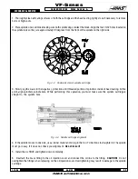
1. Thoroughly clean all mating surfaces of both the cartridge and the head casting, lightly stone if necessary to remove
burrs or high spots.
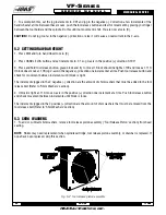
2. Place spindle on wood block making sure both spindle dogs contact the block. Align the two 10-32 holes located on
the spindle lock so they are approximately 90 degrees from the front of the spindle on the right side.
Fig. 4-3 Underside view of spindle cartridge.
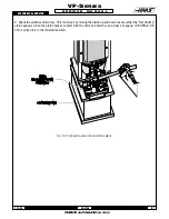
3. Slowly jog the Z-axis in the negative (-) direction until threaded portion of spindle is inside of head casting. At this
point, align spindle to spindle bore. While performing this operation, you must make sure the spindle cartridge is
straight to the spindle bore.
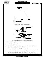
Fig. 4-4 Spindle cartridge alignment.
4. If the spindle moves to one side, use a rubber mallet and/or jog in the X or Y directions to straighten it. The spindle
must go in easy. If it does not, check your alignment.
Do not force it!
5. Install the six SHCS and tighten down completely.
6. Reattach the brass fitting to the oil injection cover and connect the oil line to the fitting.
CAUTION!
Do not
overtighten the fittings when replacing on the oil injection cover. Overtightening may result in damage to the spindle
cartridge.
Summary of Contents for VF-SERIES
Page 180: ...1 15 96 96 8100 177 TABLEOFCONTENTS TECHNICAL REFERENCE SERVICE M A N U A L VF SERIES ...
Page 235: ...96 8100 1 15 96 232 VF SERIES S E R V I C E M A N U A L ASSEMBLY DRAWINGS VF 1 COLUMN ...
Page 237: ...96 8100 1 15 96 234 VF SERIES S E R V I C E M A N U A L ASSEMBLY DRAWINGS VF 1 LEADSCREW ...
Page 239: ...96 8100 1 15 96 236 VF SERIES S E R V I C E M A N U A L ASSEMBLY DRAWINGS VF 3 COLUMN ...
Page 241: ...96 8100 1 15 96 238 VF SERIES S E R V I C E M A N U A L ASSEMBLY DRAWINGS VF 3 LEADSCREW ...
Page 245: ...96 8100 1 15 96 242 VF SERIES S E R V I C E M A N U A L ASSEMBLY DRAWINGS 3 4 2 1 ...

