1-15-96
96-8100
HAAS
AUTOMATION, INC.
55
MECHANICAL SERVICE
S E R V I C E M A N U A L
VF-S
ERIES
12.
Refer to appropriate section, and install the spindle cartridge. The tool release piston will have to be reinstalled at
this time.
13. Install a tool holder with no cutter into the spindle taper.
14. Remove the tool release piston.
15. Install the snap ring on the spindle shaft.
16. Reinstall the tool release piston.
17. Finish installation of the spindle, beginning with "Spindle sweep adjustment".
18. Set the drawbar height, clamp and unclamp switches, as described in the following section.
CAUTION!
Step 20 must be followed or damage to the ATC will result.
19. Refer to "Spindle Orientation" and set the spindle orientation.
20. Reinstall the head covers.
21. Test-run the machine and perform the necessary ATC adjustments in the "Automatic Tool Changer" section.
4.4 SPINDLE SWEEP ADJUSTMENT
NOTE:
The machine must be properly leveled for the spindle sweep adjustment to be accurate.
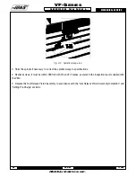
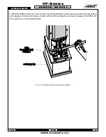
1. To check spindle sweep, place a .0005 indicator on a suitable holder, place on spindle nose and jog the Z-axis in the
negative (-) direction enough so that you can adjust the indicator to sweep a 5" radius from the center of X and Y axes'
travels. Slowly jog Z-axis in the negative (-) direction to zero out indicator.
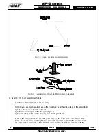
2. Establish reference zero at rear of the table. Sweep the three remaining points (left, front, and right) and record the
reading.
Summary of Contents for VF-SERIES
Page 180: ...1 15 96 96 8100 177 TABLEOFCONTENTS TECHNICAL REFERENCE SERVICE M A N U A L VF SERIES ...
Page 235: ...96 8100 1 15 96 232 VF SERIES S E R V I C E M A N U A L ASSEMBLY DRAWINGS VF 1 COLUMN ...
Page 237: ...96 8100 1 15 96 234 VF SERIES S E R V I C E M A N U A L ASSEMBLY DRAWINGS VF 1 LEADSCREW ...
Page 239: ...96 8100 1 15 96 236 VF SERIES S E R V I C E M A N U A L ASSEMBLY DRAWINGS VF 3 COLUMN ...
Page 241: ...96 8100 1 15 96 238 VF SERIES S E R V I C E M A N U A L ASSEMBLY DRAWINGS VF 3 LEADSCREW ...
Page 245: ...96 8100 1 15 96 242 VF SERIES S E R V I C E M A N U A L ASSEMBLY DRAWINGS 3 4 2 1 ...


