96-8100
1-15-96
68
MECHANICAL SERVICE
HAAS
AUTOMATION, INC.
S E R V I C E M A N U A L
VF-S
ERIES
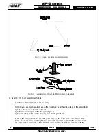
Fig. 8-2 Support base/mast support assembly.
Fig. 8-3 Exploded view of boom modification plate components.
3. Assemble the boom assembly as follows:
A. Lubricate the components of the assembly:
1) Using a grease brush, apply grease to the through-hole and the side surface of the pulley wheel.
2) Wipe a thin coat of oil on the entire cable.
3) Lubricate all clevis pins with a thin layer of grease.
4) Oil all bearings on the winch and apply grease to the gear teeth.
B. Place the pulley wheel inside the cable guide and place this subassembly into the end of the
boom. Ensure the clevis pin through-hole is toward the top of the boom and the rounded end of
the cable guide is toward the outside. Slide the clevis pin through the hole and fasten with the
Summary of Contents for VF-SERIES
Page 180: ...1 15 96 96 8100 177 TABLEOFCONTENTS TECHNICAL REFERENCE SERVICE M A N U A L VF SERIES ...
Page 235: ...96 8100 1 15 96 232 VF SERIES S E R V I C E M A N U A L ASSEMBLY DRAWINGS VF 1 COLUMN ...
Page 237: ...96 8100 1 15 96 234 VF SERIES S E R V I C E M A N U A L ASSEMBLY DRAWINGS VF 1 LEADSCREW ...
Page 239: ...96 8100 1 15 96 236 VF SERIES S E R V I C E M A N U A L ASSEMBLY DRAWINGS VF 3 COLUMN ...
Page 241: ...96 8100 1 15 96 238 VF SERIES S E R V I C E M A N U A L ASSEMBLY DRAWINGS VF 3 LEADSCREW ...
Page 245: ...96 8100 1 15 96 242 VF SERIES S E R V I C E M A N U A L ASSEMBLY DRAWINGS 3 4 2 1 ...


