96-8100
1-15-96
70
MECHANICAL SERVICE
HAAS
AUTOMATION, INC.
S E R V I C E M A N U A L
VF-S
ERIES
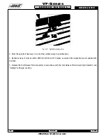
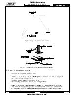
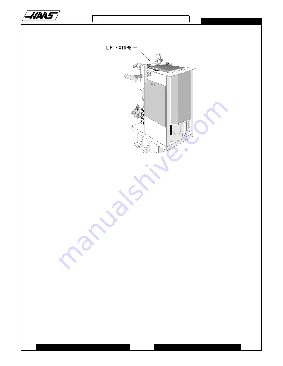
Fig. 8-5 View of transmission lift fixture.
8.4 TRANSMISSION REMOVAL
NOTE:
This procedure is not for VF-O.
1. Ensure the VMC is ON. You will need to raise and lower the head stock to remove the transmission. At this time, raise
the Z-axis to the full up position.
2. Remove the cover panels from head stock area ("Head Covers Removal" section).
3. If machine is equipped with the Through the Spindle Coolant option, remove the pressure regulator, check valve
assembly, and bracket from the old transmission, so they can be installed later on the new transmission.
4. Remove the tool release piston assembly ("Tool Release Piston" section).
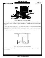
5. Remove the six SHCS holding the transmission to the head casting. Slide the transmission forward enough to
release the drive belt from the transmission and spindle pulleys.
6. Press the POWER OFF button on the control panel and turn the main breaker off. If there is an external breaker box,
turn it off and lock it up.
7. Disconnect all electrical lines and air lines from the transmission solenoid bracket. Disconnect the electrical and oil
lines from the oil pump. Plug the oil lines to prevent contamination. Most of the lines should be marked and identified.
If not marked, do so as it is removed.
Summary of Contents for VF-SERIES
Page 180: ...1 15 96 96 8100 177 TABLEOFCONTENTS TECHNICAL REFERENCE SERVICE M A N U A L VF SERIES ...
Page 235: ...96 8100 1 15 96 232 VF SERIES S E R V I C E M A N U A L ASSEMBLY DRAWINGS VF 1 COLUMN ...
Page 237: ...96 8100 1 15 96 234 VF SERIES S E R V I C E M A N U A L ASSEMBLY DRAWINGS VF 1 LEADSCREW ...
Page 239: ...96 8100 1 15 96 236 VF SERIES S E R V I C E M A N U A L ASSEMBLY DRAWINGS VF 3 COLUMN ...
Page 241: ...96 8100 1 15 96 238 VF SERIES S E R V I C E M A N U A L ASSEMBLY DRAWINGS VF 3 LEADSCREW ...
Page 245: ...96 8100 1 15 96 242 VF SERIES S E R V I C E M A N U A L ASSEMBLY DRAWINGS 3 4 2 1 ...

