background image

Installation of gear reducer

5

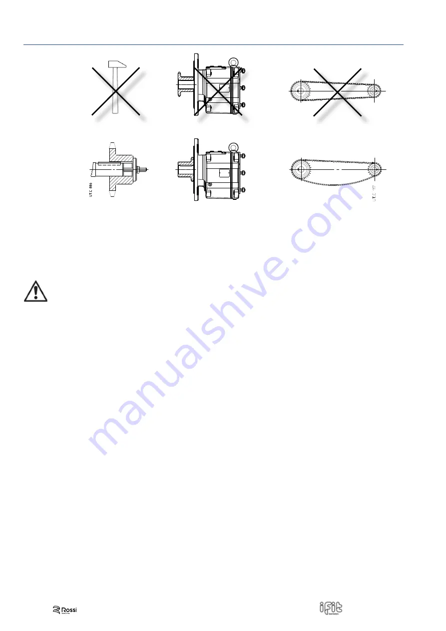
Incorrect

Correct

UT

.C. 2437

Generally, it is recommended to machine the hole of parts keyed onto shaft end, tolerance 

H7

.

For low speed shaft ends, provided that load is not uniform and light, tolerance must be 

K7

.

Before  mounting,  thoroughly  clean  mating  surfaces  with  proper  antirust  products,  and  lubricate  against  seizure  and  fretting 

corrosion.

  Attention!

Assemble and disassemble with the aid of 

jacking screws

 and 

pullers

 using tapped holes at shaft butt-end, taking 

care to avoid impacts and shocks which may

 irremediably damage the bearings, the circlips or other parts.

For couplings H7/m6 and K7/j6 it is advisable that the part to be keyed is preheated to a temperature of 80 ÷ 100 °C.
The couplings having a tip speed on external diameter up to 20 m/s must be statically balanced; for higher tip speeds they must 

be dynamically balanced. 
Where the transmission link between gear reducer and machine or motor generates shaft end loads, ensure that: loads do not 

rise above catalog values:

• 

loads do not rise above catalog values;

• 

transmission overhang is kept to a minimum;

• 

drive-chains should not be tensioned (if necessary – alternating loads and/or motion – foresee suitable chain tighteners);

• 

in the gear transmission systems there is a proper backlash (≈ 0,03 ÷ 0,04 mm) between pinion and rack;

• 

drive-belts should not be over-tensioned.

18

UT.D 208-2021.12-EN

Summary of Contents for Rossi IFIT Series

Page 1: ...Operating instructions Series UT D 208 2021 12 EN ...

Page 2: ...2 UT D 208 2021 12 EN ...

Page 3: ...esignation 10 4 Lifting handling and storing 12 4 1 Lifting and handling 12 4 2 Storage 13 5 Installation of gear reducer 14 5 1 General 14 5 2 Tightening torques for fastening bolts feet flange accessories and for plugs 15 5 3 Flange mounting 16 5 4 Foot mounting 16 5 5 Fitting of components to shaft ends 17 6 Lubrication 19 6 1 General 19 6 2 Lubrication table 20 6 3 Oil level quantity 22 6 4 Mou...

Page 4: ...or to adapter 26 8 Commissioning 27 8 1 General 27 8 2 Running in 27 9 Maintenance 28 9 1 General 28 9 2 Oil change 28 9 3 Seal ring 29 9 4 Bearings 29 9 5 Metal filler plug with filter and valve 29 9 6 Sound levels LWA and LpA 29 9 7 Spare part tables 30 10 Gear reducer troubles causes and corrective actions 32 11 Index of revisions 33 Contents 4 UT D 208 2021 12 EN ...

Page 5: ...The paragraphs marked with symbols shown below contain dispositions to be strictly respected in order to assure personal safety and to avoid any heavy damages to the machine or to the system Electric or mechanical danger such as the elements of housing gear pairs shafts and bearings of gear reducer must be transformed into steel scraps as well as cast iron elements subject to other specific require...

Page 6: ...nal information Attention For the installation use and maintenance of the electric motor standard brake or non standard motor or the possible motor variator and or the electric supply device frequency converter soft start etc and or any optional electric devices e g independent cooling unit etc consult the specific attached documentation Request it if necessary Maintenance safety When operating on ...

Page 7: ...mounted gear units provide appropriate safety devices against loosening or breaking of the mounting screws rotation or loosening of the gear unit from the machine pin due to accidental breakage of the reaction constraint accidental breakage of the machine pin Movable elements Provide safety guards for unused shaft ends and accessible fan cover passages or others Any operation on the gear reducer o...

Page 8: ...ntest such damage to the carrier Do not commission gear reducers and gearmotors that are even slightly damaged Report any non compliance to Rossi 3 2 Name plate Each gear reducer is provided with a name plate in anodized aluminium containing main informations necessary for a correct identification of the product see ch 3 6 the name plate must not be removed and must be kept integral and readable Al...

Page 9: ...to ISO 12944 2 Overpaintable only with dual compound products 1 Machined parts remain unpainted they are protected with an easily removable antitrust oil before painting remove the protective oil Overhanging free shaft ends and hollow shafts are treated with protective anti rust long life oil and protected with a a plastic polyethylene cap All internal parts are protected with protective anti rust...

Page 10: ...n compact motor Motor adapter code 2 3 4 5 iC Gear reducers Coaxial i FIT 6 7 8 9 7 P Performance foot mounting J Performance with flange E Metric 3 37 4 00 B3 B6 B7 B8 V5 V6 F212 F214 B12B B30M gear reducer AB12BI063 B16D AB16BI063 configuration with adapter and standard IEC motor configuration with compact motor IEC AB12BN056 NEMA 2 Stages reduction 3 Stages reduction AB12CN143 AB30MN324 AB12BI071 ...

Page 11: ...B2 TB3 230 400 400 B12B B30C B5 Drive end D Non drive end N UT C 2383 The designation is to be completed with the statement of motor terminal box position if differing from the standard one TB0 The release lever for brake motor follows the position of the terminal box The cable entry is the responsibility of the Buyer the terminal box is integral with housing with knockout cable openings on both si...

Page 12: ...haft ends Do not use motor eyebolts Do not use front threads of shaft ends or eventual external pipes Do not add supplementary loads to the gear reducer or gearmotor mass Attention During the lifting and handling do not stand under the suspended loads do not damage the gear reducer with an inadequate transport keep the gear reducers filled with oil in the mounting position foreseen in the order Gea...

Page 13: ...oosen the closed plugs or activate the drain plug before commissioning In the event of Long germ storage option for a storage period from 12 to 24 months in normal environments the following is envisaged gear reducer delivered without oil filling internal volume of the gear reducer protected by VI lubricant coating application of a layer of special anti corrosive oil to all unpainted external parts...

Page 14: ...ucer and eventual flange B5 it is recommended to use locking adhesives such as LOCTITE on the fastening screws also on flange mating surfaces For accessories not supplied by Rossi pay attention to their dimensioning consult us if need be Before wiring up the gearmotor make sure that motor voltage corresponds to input voltage If direction of rotation is not as desired invert two phases at the termina...

Page 15: ...plugs Unless otherwise specified it is normally sufficient to use class 8 8 screws the following cases are an exception for which screws with strength class 10 9 must be used iC 372 iC 373 FE with flange F312 iC 472 iC 473 FE with flange F414 iC 572 iC 573 FE with flange F516 Before tightening carefully degrease the screws in the event of heavy vibrations heavy duties frequent drive inversions apply a t...

Page 16: ...M8 9 35 iC 37 iC 47 140 M8 10 35 iC 27 iC 57 160 M8 10 35 iC 37 iC 67 200 M10 12 70 iC 57 iC 77 250 M12 15 120 iC 77 300 M12 15 120 iC 87 300 M12 16 120 iC 87 350 M12 15 120 iC 97 350 M16 18 290 iC 97 450 M16 22 338 UT C 2435 Frame size gear reducer Foot mounting screw UNI5737 minimum length in mm iC 27 iC 37 M8 x 18 iC 47 iC 57 M12 x 24 iC 67 M12 x 30 iC 77 M16 x 30 iC 87 M16 x 45 iC 97 M20 x 55 ...

Page 17: ...36 60 1 2 13 10 7 10 18 5 29 5 0 25 6 35 0 25 6 35 1 688 42 86 0 25 6 35 0 141 3 58 1 367 34 72 1 375 34 93 2 76 70 1 2 13 10 7 10 18 5 29 5 0 313 7 94 0 313 7 94 1 813 46 04 0 313 7 94 0 174 4 42 1 518 38 56 1 625 41 28 3 15 80 5 3 11 13 5 50 23 36 8 0 375 9 52 0 375 9 52 2 25 57 15 0 375 9 52 0 209 5 31 1 796 45 62 2 125 53 93 3 94 100 3 4 10 16 5 15 26 42 2 0 50 12 7 0 50 12 7 2 625 66 68 0 50 ...

Page 18: ...or other parts For couplings H7 m6 and K7 j6 it is advisable that the part to be keyed is preheated to a temperature of 80 100 C The couplings having a tip speed on external diameter up to 20 m s must be statically balanced for higher tip speeds they must be dynamically balanced Where the transmission link between gear reducer and machine or motor generates shaft end loads ensure that loads do not...

Page 19: ...fig 6 1 1 It is necessary to keep the breather free from dirt that could compromise its functionality If this is not possible please contact Rossi S p A to find a different solution The lubricant quantity to add shall be the one that will allow you to reach the required level shown in the middle of the plug with the gear reducer not running and not the indicative quantity mentioned in the catalog Fig...

Page 20: ... Optiflex A Alpha SP FUCHS Renolin Unisys Renolin PG Renolin CLP Manufacturer Oil synthetic PAO Oil synthetic PAG Oil mineral KLÜBER Klübersynth GEM4 Klübersynth GH6 Klübersynth GEM1 MOBIL Mobil SHC Gear Mobil Glygoyle Mobilgear 600 XP SHELL Omala S4 GX Omala S4 WE Omala S2 G TEXACO Pinnacle Synlube CLP Meropa TOTAL Carter SH Carter SY Carter EP ISO viscosity grade Unless otherwise specified the gea...

Page 21: ... NBU 8 EP Attention Refer to ch 6 4 for bearings requiring greasing and contact Rossi in case of doubt Lubrication 6 Oil change interval An overall guide to oil change interval is given in the table and assumes pollution free surroundings When heavy overloads are present halve the values Seal rings Duration depends on several factors such as dragging speed temperature ambient conditions etc as a r...

Page 22: ...r to measure the oil level quantity 90 UT C 2438 Fig 6 3 1 Gear reducer oil quantity Compare the x value measured as in Fit 6 3 1 with the max value provided by table 6 3 2 Adjust the amount of oil if necessary Frame size gear reducer Oil quantity l B3 B6 B7 B8 V5 V6 iC 272 iC 273 0 25 0 5 0 5 0 5 0 7 0 7 iC 372 iC 373 0 3 0 75 0 95 0 95 1 05 0 85 iC 472 iC 473 0 7 1 5 1 5 1 5 1 65 1 6 iC 572 iC 5...

Page 23: ... livello lato opposto scarico lato opposto sfiato lato opposto breather plug oil level plug oil drain plug sfiato livello scarico livello lato opposto scarico lato opposto sfiato lato opposto breather plug on opposite side not in view oil level plug on opposite side not in view oil drain plug on opposite side not in view Possible high oil splash for the corrective factor ft3 of nominal thermal pow...

Page 24: ...t in view oil level plug on opposite side not in view oil drain plug on opposite side not in view Possible high oil splash for the corrective factor ft3 of nominal thermal power PTN iC 27 breather plugs not present for B3 B8 B6 B7 iC 27 oil level and drain plugs not present iC 47 iC 57 oil level plug not present for B6 1 The customer is responsible for cable connection the terminal box is incorpor...

Page 25: ...prevent contact oxydation insert the motor up to shoulder do not force the motor shaft during gear reducer coupling danger of serious damages 7 2 Procedures of assembling the cylindrical pinion splined to the motor shaft UT C 2439 The following assembly procedures involving the drive shaft must be performed in the order shown 1 mount the supplied key in the groove provided 2 spline the preheated p...

Page 26: ...rs ft lb N m 3 8 16 32 9 44 6 1 2 13 80 3 109 5 8 11 157 213 In order to prevent harmful moisture or dirt e g dust infiltrations inside the adapter it is advisable to insulate any discontinuities or openings in the coupling surfaces between the motor and the adapter flange by applying a continuous bead of sealant e g LOXEAL 58 14 Prior to fitting the customer supplied motor verify that the static ben...

Page 27: ...oning 8 8 1 General Carry out an overall check making particularly sure that the gear reducer is filled with lubricant Where Y Δ starting is being used input voltage must match the motor lower voltage Δ connection For asynchronous three phase motor if the direction of rotation is not as desired invert two phases at the terminals 8 2 Running in It is advisable to execute a running in of approximatel...

Page 28: ...e oil collection system unscrew the drain plug and the filler plug in order to facilitate the draining dispose of the waste lubricant according to the laws in force wash the inside part of gear reducer housing using the same oil type suitable for the running the oil used for this wash can be applied for further washings after proper filtering by 25 µm of filtration standard Fill the gear reducer with...

Page 29: ...ad of the driven machine the transmission ratio etc and with different lubricants oil bath oil splash grease oil circulation etc it is not possible to define any periodical maintenance and replacement of bearings in advance If precautionally maintenance is required undertake periodical checks to verify noise level and vibration with the help of appropriate diagnostic equipment and instruments If the...

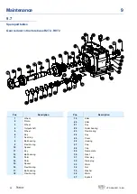
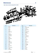
Page 30: ...earing 9 Flexible ring 10 Spacer 11 Key 12 Ball bearing 13 Shim 14 Shim 15 Spacer 16 Flexible ring 17 Ball bearing 18 Flexible ring Pos Description 19 Shim 20 Shim 21 Key 22 Roller bearing 23 Flexible ring 24 Key 25 Cover 26 Housing 27 Cap 28 Cap 29 Name plate 30 Rivet 31 Filler plug 32 Drain plug 33 Worm 34 Nut 35 Washer 36 Worm 37 Eyebolt 30 UT D 208 2021 12 EN ...

Page 31: ... 18 Flexible ring 19 Flexible ring 20 Shim 21 Shim 22 Ball bearing 23 Key 24 Roller bearing 25 Spacer 26 Ball bearing Pos Description 23 Key 24 Roller bearing 25 Spacer 26 Ball bearing 23 Key 24 Roller bearing 25 Spacer 26 Ball bearing 27 Key 28 Shim 29 Flexible ring 30 Flexible ring 31 Key 32 Cover 33 Housing 34 Cap 35 Cap 36 Name plate 37 Rivet 38 Filler plug 39 Drain plug 40 Worm 41 Nut 42 Wash...

Page 32: ...r spallings excessive flanks roughness Consult Rossi Bearings failure defect or bad lubrication Consult Rossi Taper roller bearings with excessive clearance Consult Rossi Vibrations Check the fastening and the bearings Lubricant leaking from seal ring Seal ring with worm bakelized damaged or false mounted seal lip Replace seal ring see ch 11 4 Damaged raceway surface scoring rust dent etc Restore t...

Page 33: ...Index of revisions 11 33 UT D 208 2021 12 EN ...

Page 34: ...34 UT D 208 2021 12 EN ...

Page 35: ...35 UT D 208 2021 12 EN ...

Page 36: ...ormation contained in this publication however Rossi can accept no responsibility for any errors omissions or outdated data Due to the constant evolution of the state of the art Rossi reserves the right to make any modification whenever to this publication s contents The responsibility for the product selection is of the Customer excluding different agreements duly legalized in writing and undersign...

Reviews: