21
Rossi
Operating instructions − UTD.045.06-2013.00_TR_EN
TR
EN
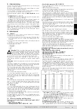
8 - Commissioning
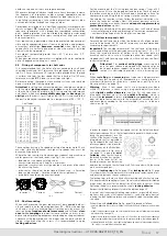
Carry out an overall check, making particularly sure that the gear
reducer is filled with lubricant.
Where star-delta starting is being used, input voltage must match
the motor lower voltage (
Δ
connection).
For asynchronous three-phase motor, if the direction of rotation is
not as desired, invert two phases at the terminals.
Before running gear reducers fitted with
backstop device
, see ch.
5.5.
A
running-in
period is advisable:
– of approx. 400
÷
1 600 h for gear reducers with worm gear pairs
in order to reach maximum efficiency;
– of approx. 200
÷
400 h for gear reducers with bevel and/or cylin-
drical gear pairs in order to reach maximum functionality.
The temperature of both gear reducer and lubricant may well rise
beyond normal values during running-in. After the running-in period
it may be necessary to verify the gear reducer fastening bolt tight-
ness.
Note: worm gear reducer efficiency is lower in the
first running
hours
(about 50) and at every cold starting (efficiency will be better
with oil temperature increasing). For further information consult
Rossi technical catalogs.
9 - Maintenance
9.1 - General
At machine rest, verify at regular intervals (more or less frequently
according to environment and use):
a) all external surfaces are clean and air passages to the gear redu-
cer or gearmotors are free, in order that cooling remains fully
effective;
b) oil level and deterioration degree (check with cold gear reducer
at rest);
c) the correct fastening screws tightening.
During the operation check:
– noise level;
– vibrations;
– seals;
– etc.
Attention!
After a running period, gear reducer is subject
to a light internal overpressure which may cause burning
liquid discharge. Therefore, before loosening whichever
plug wait until gear reducer has become cold; if not possi-
ble, take the necessary protection measures against burning due to
warm oil contact. ln all cases, always proceed with great care.
Maximum oil temperatures indicated in lubrication table (see
ch.6.2) do not represent a hindrance to the gear reducer regular
running.
Oil change
. Execute this operation at machine rest and cold gear
reducer.
Prearrange a proper drain oil collection, unscrew both the drain
plug and the filler plug in order to facilitate oil draining; dispose the
exhaust lubricant in compliance with the laws in force.
Wash the inside part of gear reducer housing using the same oil
type suitable for the running; the oil used for this wash can be
applied for further washings after proper filtering by 25 μm of filtra-
tion standard.
Fill in the gear reducer again up to level.
It is always recommended to replace the seal rings (see ch. 9.3)
When dismounting the cap (whenever gear reducers are provided
with), reset the sealing with adhesive on cleaned and degreased
mating surfaces.
9.2 - Coil
In case of long non-running periods at ambient temperatures lower
than 0 °C, the coil should be emptied out using compressed air to
blast out all the coolant, so as to avoid freezing-up which would
cause the coil to break.
9.3 - Seal rings
It is always recommended that the seal rings are replaced with new
ones when they are removed or during periodic checks of gear
reducer; in this case, the new ring should be generously greased
and positioned so that the seal line does not work on the same point
of sliding contact as the previous ring.
Oil seals must be protected against heat radiation, also during the
shrink fitting of parts, if applicable.
Durating depends on several factor such as dragging speed, tem-
perature, ambient conditions, ect.; as a rough guide it can vary from
3 150 to 25 000h.
9.4 - IEC motor mounting and dismounting
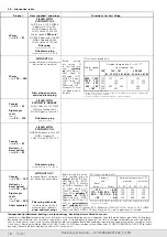
Gearmotors with motor keyed on hollow high speed shaft of
gear reducer:
– Worm gearmotors MR V
– Helical gearmotors MR 2I, MR 3I 140 ... 360
– Bevel helical gearmotors MR CI, MR C2I
– be sure that the mating surfaces are machined under accuracy
rating (IEC 60072-1);
– clean surfaces to be fit thoroughly;
– check that the fit-tolerance (push-fit) between hole and shaft end
is G7/j6 for D
≤
28 mm, F7/k6 for D ≥ 38 mm;
– lubricate surfaces to be fitted against fretting corrosion.
– when a lowered key is needed, replace the motor key with the one
supplied together with the servo gear reducer; if necessary, adjust
it accordingly to the motor shaft keyway length; check that there
is a clearance of 0,1
÷
0,2 mm between the top and the bottom
of the keyway of the hole. If shaft keyway is without shoulder, lock
the key with a pin.
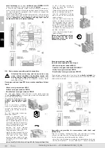
In case of
hub clamp
(helical gearmotors 2I, 3I with motor size ≥
200) assemble as follows:
– rotate the hub clamp so that the tightening screw head is aligned
with one of the input holes present on gear reducer flange, remo-
ving first the relevant plugs;
– do not modify the factory setting of hub clamp axial position as
this is the best solution in order to reach the maximum tightening
effect;
– introduce the motor from the top down to shoulder;
– lock the motor fitting screws of bolts to the gear reducer flange;
– lock the hub clamp screw by means of torque wrench until the
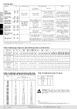
tightening torque stated in the tightening torque table (see page
24) is reached (also during this operation it is advisable not to
modify the hub clamp axial position);
– screw the hole plugs of gear reducer flange;
For the disassembly please proceed as follows:
– acting on rear motor shaft end, if possibile, or disconnecting the
gear reducer from machine and acting on gear reducer low speed
shaft (with brake motor please keep the brake released) alligning
the key hole with the locking screw of hub clamp;
– align the key through hole with the tightening screw of the hub
clamp, (trying not to modify the axial position of hub clamp);
– loosen the motor fastening bolts or nuts from gear reducer flange;
– disassemble the motor.
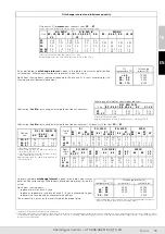
Gearmotors with cylindrical pinion keyed directly into the
motor shaft end:
– Worm gearmotors MR IV, MR 2IV
– Helical gearmotors MR 3I 40 ... 125, MR 4I
– Bevel helical gearmotors MR ICI, MR C3I
– Coaxial gearmotors
– be sure that the motor mating surfaces are machined under accu-
racy rating (IEC 60072-1);
– clean surfaces to be fitted thoroughly;
– check that the fit-tolerance (standard locking) between hole and
shaft end is K6/j6 for D
≤
28 mm, and J6/k6 for D ≥ 38 mm;
– when a lowered key is needed, replace the motor key with the one
supplied together with the servo gear reducer; if necessary, adjust
it accordingly to the motor shaft keyway length; check that there
is a clearance of 0,1
÷
0,2 mm between the top and the bottom
of the keyway of the hole. If shaft keyway is without shoulder, lock
the key with a pin.
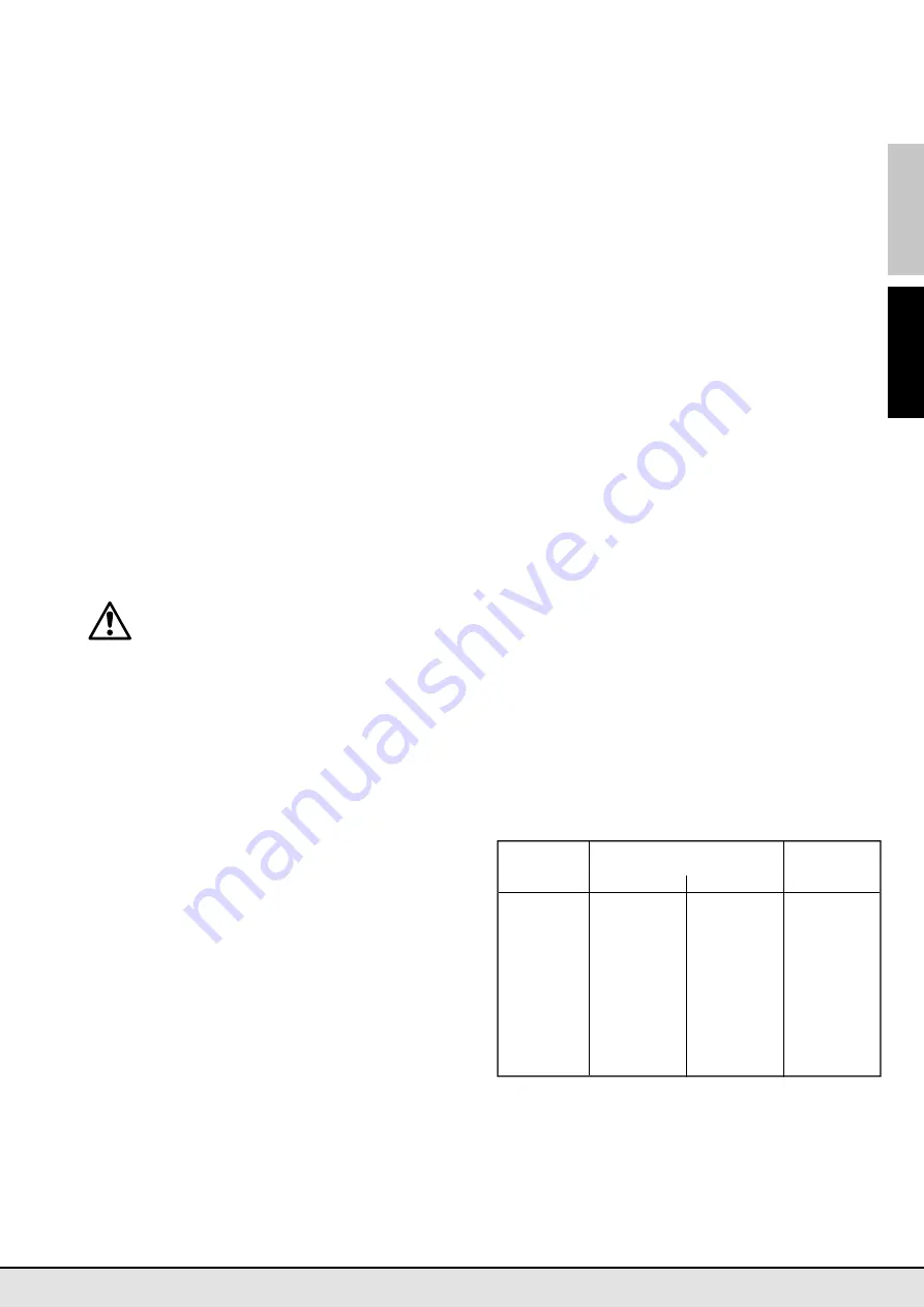
– make sure that the motors have bearing location and overhang
(distance S) as shown in the table;
Motor
Min dynamic load capacity
Max dimension
size
daN
‘S’ mm
Front
Rear
63
450
335
16
71
630
475
18
80
900
670
20
90
1 320
1 000
22,5
100
2 000
1 500
25
112
2 500
1 900
28
132
3 550
2 650
33,5
160
4 750
3 350
37,5
180
6 300
4 500
40
200
8 000
5 600
45
225
10 000
7 100
47,5
250
12 500
9 000
53
280
16 000
11 200
56
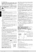
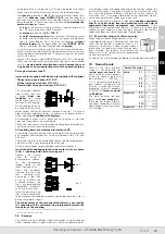
– mount onto the motor shaft as follows:
–
the spacer
pre-heated at
65° C
treating the relevant motor
shaft area with
adhesive type LOXEAL 58-14
and checking
that between keyway and motor shaft shoulder there is a cylin-
drical part ground by 1,5 mm at least; pay attention
not to
damage the external surface
of spacer;
–
the key
in the keyway, making sure that a contact length of at
least 0,9 times the pinion width is present;
– the
pinion
pre-heated at
80 ÷ 100 °C
;
–
the axial fastening system
when foreseen (self locking screw
on motor shaft butt-end with washer and spacer or hub clamp
with 1 or more dowels, fig. a); for the cases foreseen
without


