background image


25 

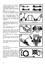
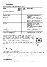
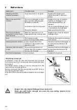
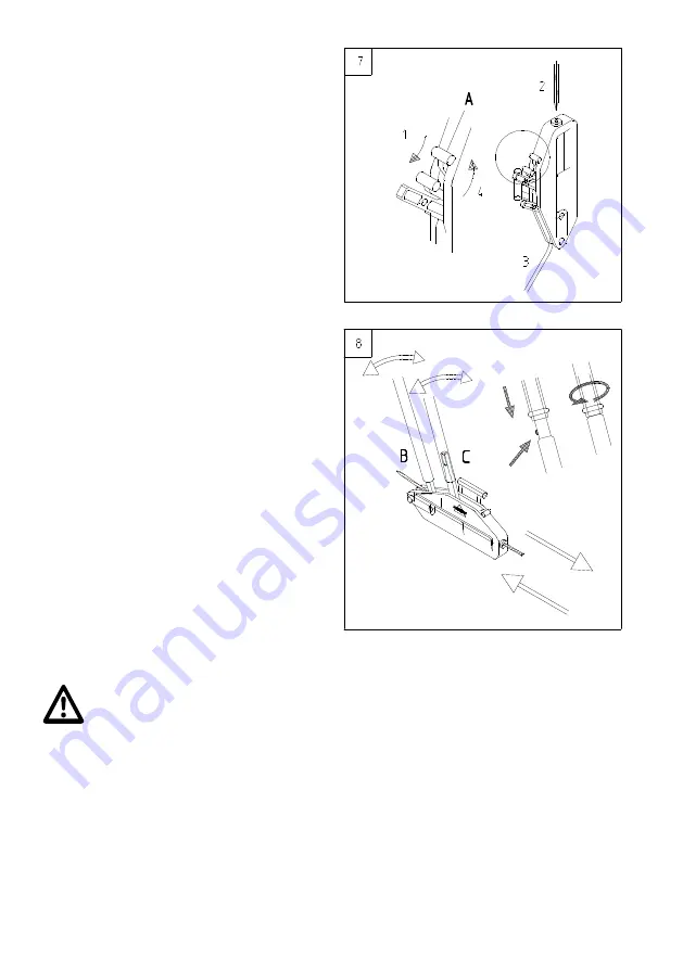
Insert the rope in the manner described below. 

Push  the forward  motion/reverse motion  lever  to 
the side where the rope enters the machine.    
Push  the  lever  to  open  the  clamping jaws  (A)  to 
the  middle  of  rope  pulling  machine  (see  Fig.  7 
(1)), and, in that position, let it lock into the upper 
catch.    
Hold the lever tightly so that it cannot snap back 
accidentally. 
 
Straighten  about  200 mm  of  the end  of  the  rope 
(2). 
Insert  the  tip  of  the  rope  into  the  guide  eye  and 
push the rope through the machine until it comes 
out  on  the  other  side  over  the  anchor  bolt.  If 
there seems to be some resistance, turn the rope 
back and forth a little bit.  
 
Pull  the  tip  of  the  rope  (3)  through  the  machine 
until the rope exhibits a little tension. 
 
Push  the jaw-opening  lever  (A)  out  of  the  catch, 
see  Fig.  7  (4).  Hold  the  lever  tightly  so  that  it 
cannot snap back accidentally. 
 
Push the telescope lever onto the forward motion 
lever (B) of the rope pulling machine and secure 
by  turning  in  any  direction,  see  Fig.  8  on  the 
right. 
 
Move the rope forward by moving the lever back 
and forth in steady and long movements. 
 
When  a  load  is  to  be  lowered,  place  the 
telescope  lever  onto  the  backward  motion  lever 
(C)  of  the  rope  pulling  machine  and  secure  by 
turning in any direction, see Fig. 8. 
 
Move  the  rope  backwards  by  moving  the  lever 
back and forth in steady and long movements. 


Danger! Before the end of the rope reaches the machine (min. 0.5 m should still 
be available): Stop unwinding the rope. Danger of crashing! 


When there no longer is any load on the pulling rope, it can be removed from the machine as follows: 
Push the forward motion/reverse motion lever to the side where the rope enters the machine. Shift the 
jaw  opening  lever  (A)  from  the  operating  position  to  the middle  of  the  rope  pulling  machine  and  let  it 
lock  into  the  catch  in  this  position,  see  Fig.  7.  Hold  the  lever  tightly  so  that  it  cannot  snap  back 
accidentally. 
Pull the wire rope out of the machine. 
Shift the jaw opening lever (A) back into the operating position, see Fig. 6. Hold the lever tightly so that 
it cannot snap back accidentally. 

Summary of Contents for HIT 6

Page 1: ...1 HIT 6 10 16 32 HIT 10 Special Bruksanvisning Operating manual THUN SWITZERLAND ...

Page 2: ...vegelse bakover Reverse motion lever 7 Brytesplint overlast Shear pin overload 8 Spak for bevegelse fremover Forward motion lever 9 Teleskopspak Telescope lever 10 Den spissede enden av ståltauet som føres gjennom taljen End of rope that is running out 11 Forankringsbolt Anchoring bolt 12 Hus Housing 13 Merkeplate Typeplate 14 Bærehåndtak ikke HIT 6 Carrying handle except HIT 6 ...

Page 3: ...3 Bruksanvisning Habegger Wire jekke talje HIT fra side 5 Operating manual for Habegger Wire rope hoist HIT as of page 23 ...

Page 4: ...4 Kontroller i henhold til kapittel 6 Checks according to chapter 6 Type HIT Serie No Date Dato Remark bemerkninger Signature Signatur ...

Page 5: ...henhold til det taljen er konstruert for 7 2 2 Sikkerhetsreglene i denne brukerveiledningen 7 2 3 Generelle sikkerhetsregler 8 2 3 1 Arbeidsstedet 8 2 3 2 Forankring 8 2 3 3 Ståltauet 9 2 3 4 Lasten 9 2 3 5 Trekking løfting senking og sikring 10 2 4 Garanti og erstatningsansvar 10 3 Tekniske data 11 4 Drift 11 5 Feil 14 6 Vedlikehold 15 7 Avhendig 15 Reservedelsliste 28 31 ...

Page 6: ...ssige arbeidsmetoder følges Vi håper at arbeidet med dette HABEGGER produktet vil være givende og vellykket EU samsvarserklæring for Wire jekke taljer av typen HIT 6 HIT 10 HIT 10 Special HIT 16 og HIT 32 oversatt versjon Vi HABEGGER Maschinenfabrik AG Mittlere Strasse 66 CH 3600 Thun Sveits erklærer med dette at maskinen taljen som er beskrevet i dette dokumentet overholder de grunnleggende krave...

Page 7: ...st lukkes begge klemkjevesettene automatisk og belastningen fordeles da på begge klemkjevene 2 Sikkerhetsregler Kun feilfrie wire jekke taljer skal benyttes Følg alltid instruksjonene i brukerveiledningen Habeggers HIT wire jekke taljer representerer det nyeste innen denne typen utstyr Lover forskrifter og sikkerhetsutstyr gir ingen beskyttelse mot uforsiktighet og uaktsomhet Før du utfører arbeid...

Page 8: ... objekter Tekniske forankringspunkter Habegger forankringsskinner med påler steinforankring betingforankring rundt treanker som er nedgravd i jorden Disse forankringstypene er avhengige av kvaliteten på underlaget Bruk tilstrekkelig kraftige stropper eller kabler for å feste maskinen til forankringsbolten Fest alltid wire jekke taljen i forankringsbolten Sett aldri wire jekke taljen på ståltauinnf...

Page 9: ...lsen eller enden av ståltauet Reduser lengden på ståltauet om mulig Skift ut eller reparer kroken hvis kroksperren mangler Skift ut ståltauet dersom det er slitt mer enn 10 av den nominelle diameteren på det tynneste punktet Ikke la ledd hylser trykkdeler korte skjøter osv gnisse mot ståltauet Når ståltauet må føres over skarpe kanter hindringer osv må det beskyttes ved hjelp av ruller eller puter...

Page 10: ...s detektorer for ståltauet Når du senker lasten må du passe på at ståltauet er langt nok Stopp den siste 0 5 m før enden av ståltauet og plasser en støtte under lasten eller fest den på nytt 2 4 Garanti og erstatningsansvar Habegger garanterer kostnadsfri erstatning av deler samt montering og demontering av disse delene i tilfeller der det kan bevises at delene har blitt ubrukelige som følge av ma...

Page 11: ...t uten ståltau HIT 10 Special 4 2 kg 6 5 kg 7 1 kg 12 kg 21 5 kg Dimensjoner Bredde Lengde Høyde 100 mm 352 mm 210 mm 100 mm 430 mm 242 mm 120 mm 550 mm 300 mm 150 mm 685 mm 330 mm Ekstra skjærbolter i håndtak for ståltauinnføring i bærehåndtaket Ståltau for HIT 6 HIT 10 HIT 16 HIT 32 Ståltaudiameter 6 4 mm 8 4 mm 11 2 mm 16 2 mm Minimum ståltaudiameter ved nominell belastning 5 8 mm 7 6 mm 10 1 m...

Page 12: ...ten med Velg en plassering for taljen som gir gode forankringsmuligheter Fest wire jekke taljen med egnet festeutstyr på en slik måte at den kan justere seg i samme retning som lasten skal beveges se venstre del av fig 5 Før lastebolten helt inn i sidene på huset Fest bolten som foreskrevet ved å dreie den 180 to ganger se høyre del av fig 5 Velg en dreibar lastekrok med låseleppe når du bruker Fi...

Page 13: ...ås den der ved å dreie den i en hvilken som helst retning se høyre del av fig 8 Beveg ståltauet fremover ved å føre spaken frem og tilbake med lange og jevne bevegelser Når en last skal senkes plasseres teleskopspaken inn på wire jekke taljens retningsspak for bevegelse bakover C og deretter låses den ved at den dreies i hvilken som helst retning Se figur 8 Beveg ståltauet bakover ved å føre spake...

Page 14: ...t rengjør den og smør den med olje Taljehuset er bøyd eller ødelagt Det var ikke mulig for taljen å justere seg selv i den retningen som lasten ble trukket Send taljen til din Habegger forhandler eller et autorisert verksted for reparasjon Forankringsbolten eller huset er bøyd Forankringsbolten ble ikke skjøvet igjennom på riktig måte eller den var ikke riktig festet Send taljen til din Habegger f...

Page 15: ...kyndig virksomhet se merket på wire jekke taljen Under denne inspeksjonen må alle deler kontrolleres med tanke på deformering slitasje og oppflising Testresultatene må føres inn i en testbok eller på side 4 i dette heftet Brukeren er ansvarlig for at slike inspeksjoner utføres regelmessig Det bør dessuten utføres ekstra inspeksjoner av fagfolk i henhold til gjeldende lokale regler eller hvis wire ...

Page 16: ...16 Merknader Notice ...

Page 17: ...ccording to the intended purpose 19 2 2 Safety instructions in this operating manual 19 2 3 General safety instructions 20 2 3 1 Location 20 2 3 2 Anchorage 20 2 3 3 Pulling rope 21 2 3 4 Load 21 2 3 5 Pulling lifting lowering and securing 22 2 4 Warranty and liability 22 3 Technical data 23 4 Operation 23 5 Malfunctions 26 6 Maintenance 27 7 Disposal 27 Lists of spare parts 28 31 ...

Page 18: ...valent in the country of use and at the work site the acknowledged technical rules for working safely and properly should be observed We hope your work with this HABEGGER product will be enjoyable and successful Translation EC Declaration of Conformity for the HIT 6 HIT 10 HIT 10 special HIT 16 HIT 32 wire rope hoists We HABEGGER Maschinenfabrik AG Mittlere Strasse 66 CH 3600 Thun Switzerland here...

Page 19: ... jaws are automatically closed and the load is distributed to both clamping jaws 2 Safety instructions Only use a wire rope hoist that is in a serviceable condition and observe the operating instructions HABEGGER s HIT wire rope hoists are state of the art equipment Laws regulations and safety devices cannot protect against carelessness and negligence Prior to working with the wire rope hoist plea...

Page 20: ...ith poles rock anchor concrete anchor round wood anchor in ground where holes can be dug These types of anchors depend on the quality of the ground Use sufficiently strong straps or loops to fasten the machine to the anchor bolt Always fasten the rope pulling machine at the anchoring bolt Never stand the rope pulling machine on the rope lead in or the housing The machine has to be able to adjust i...

Page 21: ...the rope If possible shorten the rope Replace or repair the hook if the safety catch is missing Replace the rope when it is worn by more than 10 of the nominal diameter at its thinnest point Do not let rope joinings sleeves pressure heads short splices etc run against the wire rope hoist When the rope has to be guided over sharp edges obstacles etc protect the rope by means of adequate ground roll...

Page 22: ... rope cannot by built in When you are lowering a load make sure that the rope is long enough Stop at the latest 0 5 m before the end of the rope and place a support underneath the load or reattach it 2 4 Warranty and liability Habegger grants a warranty for free of charge replacement as well as assembly and disassembly of parts when it can be proven that these parts have become unserviceable due t...

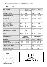
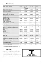
Page 23: ...pe 10 special 4 2 kg 6 5 kg 7 1 kg 12 kg 21 5 kg Dimensions Width Length Height 100 mm 352 mm 210 mm 100 mm 430 mm 242 mm 120 mm 550 mm 300 mm 150 mm 685 mm 330 mm Spare shear pins in the jaw opening lever in the carrying grip Rope for HIT 6 HIT 10 HIT 16 HIT 32 Rope Ø 6 4 mm 8 4 mm 11 2 mm 16 2 mm Minimum rope diameter under nominal load 5 8 mm 7 6 mm 10 1 mm 14 6 mm Permissible rope force 6 kN 1...

Page 24: ...mine a location for the wire rope hoist that provides good anchorage Attach the wire rope hoist with suitable fastening devices in such a way that it can adjust itself in the direction of pull see Fig 5 on the left Insert the load bolt properly into the sides of the housing Secure the bolt correctly by turning it 180 two times see Fig 5 on the right Chose a swivelling load hook with locking bar wh...

Page 25: ...nd secure by turning in any direction see Fig 8 on the right Move the rope forward by moving the lever back and forth in steady and long movements When a load is to be lowered place the telescope lever onto the backward motion lever C of the rope pulling machine and secure by turning in any direction see Fig 8 Move the rope backwards by moving the lever back and forth in steady and long movements ...

Page 26: ...housing clean and oil Housing is bent or broken It was not possible for the machine to adjust itself in the direction of pull Send the machine to Habegger or an authorized workshop to be repaired Anchoring bolt or housing is bent The anchoring bolt was not pushed through correctly or it was not secured correctly Send the machine to Habegger or an authorized workshop to be repaired Tow hook is bent...

Page 27: ...ied body see label on hoist During this inspection all parts must be checked for deformation wear and tear The test results have to be entered in a test book or on page 4 in this booklet The user is responsible for seeing to it that these inspections are carried out Furthermore additional inspections should be carried out by an expert in accordance with the local regulations or when the machine wa...

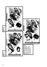
Page 28: ... 0 Ø 8 4 m m D I A 0 3 3 16 15 13 17 9 2 8 2 2 2 0 1 9 8 5 6 1 1 1 0 2 6 1 2 1 8 2 14 7 32 40 4 1 42 1 H I T 1 0 _ s p e ci a l Ø 8 4 m m D I A 0 3 3 1 6 1 5 1 3 1 7 9 2 8 2 2 2 0 1 9 8 5 6 1 1 1 0 2 6 1 2 1 8 2 1 4 7 3 2 4 0 4 1 4 2 1 3 8 3 4 HIT 6 HIT 10 HIT 10 special Bærehåndtak bakover spak Carrying handle reverse lever ...

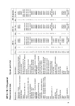
Page 29: ...n Right hand casing complete Left hand casing with name pl Carrying handle Button head rivet 6 x 14 Countersunk screw 90 M6x10 Washer Socket head cap screw Square nut M6 Front gripper assembly Rear gripper assembly Forward motion lever complete Shearing pin Jaw opening lever complete Anchor bolt complete Lever reverse motion Back push lever right hand Back push lever left hand Bolt reverse motion ...

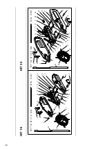
Page 30: ... 0 4 1 4 2 5 6 4 3 1 1 1 1 0 2 6 1 2 1 8 2 7 3 2 H I T 1 6 Ø 1 1 2 m m D I A 0 4 4 1 4 4 0 4 1 4 2 H I T 3 2 Ø 1 6 2 m m D I A 0 6 4 1 6 1 5 1 3 1 7 9 2 8 2 2 2 0 1 9 2 1 8 3 4 5 6 1 1 2 2 5 1 1 2 3 1 0 2 6 2 7 1 8 2 1 4 7 2 4 3 2 T h un Sw itz e r la n d ...

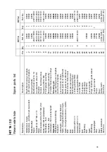
Page 31: ... head cap screw Square nut M6 M8 Front gripper assembly Rear gripper assembly Forward motion lever compl Shearing pin Jaw opening lever complete Anchor bolt complete Lever reverse motion Back push lever right hand Back push lever left hand Bolt reverse motion lever Bolt jaw opening lever Bolt back push lever Locking washer RS8 Locking washer RS9 Centre shaft Pull spindle Pulling strap Pull spindle...

Page 32: ...ilbehør for HIT16 32 Hydraulic drive available for HIT 16 32 Svivelkrok Swivel load hook Stropper og tilbehør i forskjellig utførelse Wire rope straps slings and ropes available in various versions Habegger Maschinenfabrik AG Mittlere Strasse 66 CH 3600 Thun Switzerland Telefon 41 0 33 225 44 44 Fax 41 0 33 225 44 40 E Mail info habegger hit ch Internet www habegger hit ch Thun Switzerland ...

Reviews: