background image

Unpacking 


The motherboard is shipped in antistatic packaging to avoid static damage. When unpacking the board, 

make sure that the person handling it is static protected. 


2. Memory Support 


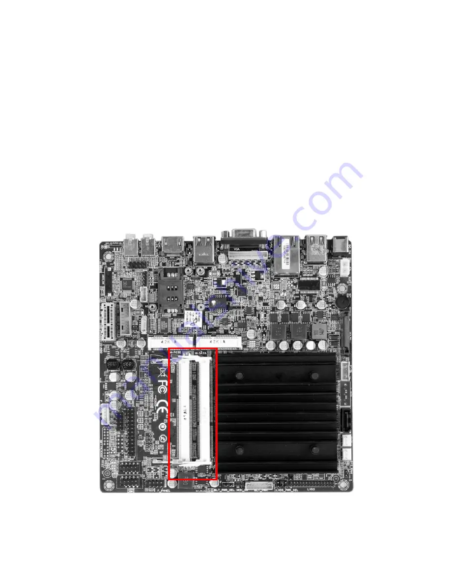
The MITX-6771 supports up to two 4 GB of DDR3L (Low Voltage) SO-DIMM of up to 1333 MHz in two 
horizontal sockets. Populate memory on Socket SO-DIMM1 first. 


2.1 Memory Population Guidelines 


Note: Be sure to use memory modules of the same type, same speed, same frequency on the same 
motherboard. Mixing of memory modules of different types and speeds is not allowed. 


Figure 1: JDIMM 


Summary of Contents for MITX-6771

Page 1: ...owing measures are generally sufficient to protect your equipment from ESD Precautions Use a grounded wrist strap designed to prevent static discharge Touch a grounded metal object before removing the board from the antistatic bag Handle the board by its edges only do not touch its components peripheral chips memory modules or gold contacts When handling chips or modules avoid touching their pins ...

Page 2: ...upport The MITX 6771 supports up to two 4 GB of DDR3L Low Voltage SO DIMM of up to 1333 MHz in two horizontal sockets Populate memory on Socket SO DIMM1 first 2 1 Memory Population Guidelines Note Be sure to use memory modules of the same type same speed same frequency on the same motherboard Mixing of memory modules of different types and speeds is not allowed Figure 1 JDIMM ...

Page 3: ...nsert the memory circuit at a 45 angle and press the circuit flat and secure it to the memory slot with an audible click on each side of the memory slot 3 Motherboard Installation The ITX 6771 motherboard has standard mini ITX mounting holes to fit different types of chassis Make sure that the locations of all the mounting holes for both motherboard and chassis match Although a chassis may have bo...

Page 4: ...ng holes on the chassis 3 Install standoffs in the chassis as needed 4 Using a phillips head screwdriver insert four Phillips head 6 screws into a mounting holes on the motherboard and its matching mounting hole on the chassis 3 2 Installing Hard Drive or SSD 1 Install mSATA SSD to the mSATA slot indicated on Figure 3 2 Install SATA hard drive or SSD by connecting the SATA power and data cable to ...

Reviews: