High Pressure Diffuser - Installation and Cleaning
K
SS -
Fe
br
ua
ry
15
, 20
06
9:
51
am
-
Ed
it
ion
2
Operator Manual
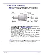
2.1.3 Diffuser Installation to Particle Counter
Install the high pressure diffuser to the particle counter by following the procedure and
below. If the counter has a 1/8” inlet tube, use a 1/4” to 1/8” tubing reducer.
1)
Verify the gasket in the VCR tube adapter is new (flat surface, no indentation). To
replace the gasket refer to
“Gasket Replacement” on page 7
2)
Using proper hardware, attach a pressurized air line (150 psi maximum) to the orifice
(#4 VCR fitting) at the “PRESSURE” end of the diffuser.
3)
Screw one end of the VCR tube adapter onto the sample tube (#4 VCR fitting), tighten
the nut on the VCR tube adapter finger-tight.
4)
While holding the sample tube nut with a wrench, tighten the nut on the VCR tube
adapter 1/8 of a turn past finger-tight.
5)
Attach tubing from the VCR tube adapter to the particle counter inlet tube. If the inlet
tube on the counter requires 1/8” tubing, insert a tubing reducer in the line.
6)
(Optional) To vent gases away from the working area, insert into the exhaust port the
hardware for venting to an environmentally safe ventilation system.
CAUTION:
To prevent contamination from entering the diffuser and particle counter through the diffuser
exhaust port, never begin a count cycle before applying pressure to the diffuser.
7)
Pressurize the sample input line then turn the particle counter on.
Fig 2-4 :
Diffuser Installation to Particle Counter

