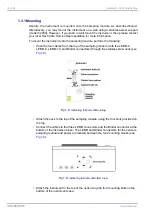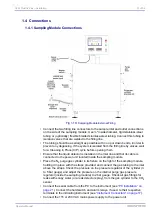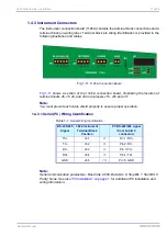
3624 ProBrix Plus - Installation
Operator Manual
ORBISPHERE
1.3 3624 Indicating Instrument Installation
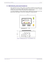
Cable glands for serial, recorder output, hold switch, and alarms are provided on the
underside of the instrument. LEMO and Binder connectors for the sensors, sampling
module, and power are inside the opening of the mounting bracket.
If mounting separately, include at least 400 mm additional frontal clearance for front
panel access, and at least 100 mm bottom clearance for cable protrusion.
Fig 1-7:
Indicating Instrument - Front and Bottom View
Summary of Contents for ORBISPHERE 3624
Page 1: ...Operator Manual ORBISPHERE 3624 Revision F 03 10 2008 ...
Page 2: ......
Page 14: ...8 of 96 Manual Overview 3624 ProBrix Plus Operator Manual ORBISPHERE ...
Page 32: ...26 of 96 Installation 3624 ProBrix Plus Operator Manual ORBISPHERE ...
Page 60: ...54 of 96 PC Program Setup 3624 ProBrix Plus Operator Manual ORBISPHERE ...
Page 68: ...62 of 96 Calibrations 3624 ProBrix Plus Operator Manual ORBISPHERE ...
Page 82: ...76 of 96 Accessories and Attachments 3624 ProBrix Plus Operator Manual ORBISPHERE ...
Page 98: ...92 of 96 Glossary 3624 ProBrix Plus Operator Manual ORBISPHERE ...
Page 101: ...3624 ProBrix Plus User Notes 95 of 96 Operator Manual ORBISPHERE User Notes ...
Page 102: ......


