3624 ProBrix Plus - Installation
Operator Manual
ORBISPHERE
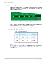
1.4.3 Instrument Connectors
The instrument connection board (1126A) contains the terminal block connections and a
terminal block pin-wiring label. Terminal block pin wiring identification is provided in the
following illustration and tables.
shows a section of the 1126A connection board, illustrating the location of
terminal blocks J6, J5, J8, and J9 and Jumpers J15, J16 and J17
Note:
You must ground each cable shield properly to ensure proper operation.
1.4.3.1 Serial (PC) Wiring Identification
Note:
Serial communication parameters - Baud rate: 9600, Data bits: 8, Stop Bit: 1, Start Bit: 0.
Parity: None. See also
, for additional PC installation and
wiring information.
Fig 1-11:
1126A Connection Board
Table 1-1:
Serial Wiring Identification
RS-422/485
Signal
3624 Instrument
Terminal Block
Position
PC RS-422/485 signal
(from Sub-D 9
connector)
TX+
J6.1
=>
Pin 1: RX+
TX-
J6.2
=>
Pin 2: RX-
RX-
J6.3
<=
Pin 3: TX-
RX+
J6.4
<=
Pin 4: TX+
GND
J6.5
<=>
Pin 5: GND
Summary of Contents for ORBISPHERE 3624
Page 1: ...Operator Manual ORBISPHERE 3624 Revision F 03 10 2008 ...
Page 2: ......
Page 14: ...8 of 96 Manual Overview 3624 ProBrix Plus Operator Manual ORBISPHERE ...
Page 32: ...26 of 96 Installation 3624 ProBrix Plus Operator Manual ORBISPHERE ...
Page 60: ...54 of 96 PC Program Setup 3624 ProBrix Plus Operator Manual ORBISPHERE ...
Page 68: ...62 of 96 Calibrations 3624 ProBrix Plus Operator Manual ORBISPHERE ...
Page 82: ...76 of 96 Accessories and Attachments 3624 ProBrix Plus Operator Manual ORBISPHERE ...
Page 98: ...92 of 96 Glossary 3624 ProBrix Plus Operator Manual ORBISPHERE ...
Page 101: ...3624 ProBrix Plus User Notes 95 of 96 Operator Manual ORBISPHERE User Notes ...
Page 102: ......

