3624 ProBrix Plus - PC Program Setup
Operator Manual
ORBISPHERE
Leaving a box unchecked will turn off the audible alarm only, but will not deactivate the
alarm itself which will still be visible in the LINE window, denoted by it's background color
(red, orange or green).
For each audible alarm, the name of the line (LINE1, LINE2, ... LINE10) will be
announced along with the message, by ticking the
Line name
box in the Sound Alarms
window. Where an audible alarm is required, it will be heard every 15 seconds until the
problem is corrected.
You can define how often the
Line on Hold
alarm is sounded, by entering a value (in
seconds) in the
Line on Hold Rate
box. This value overrides the standard delay of 15
seconds for the other alarms. The CO
2
, BRX and O
2
Error
alarm is activated when the
Sensor Out
,
Overflow
or
Incorrect Units
event occurs.
For each line, if more than one event has triggered a simultaneous error, the alarm with
the highest priority will be the one heard (P0 > P1 > P2 > P3).
Alarm priorities are defined as follows:
• Line off/Hold = P0
• Error = P1
• High/High and Low/Low = P2
• High and Low = P3
If there are warnings of the same priority, the following order will be respected:
1) Brix
2) CO
2
3) O
2
4) Temperature
For example if there are simultaneous
CO2 High/High
(P2) and
Brix Error
(P1) alerts,
then the
Brix
warning will be the one triggered, and if there are simultaneous
O2 High
(P3) and
CO2 High
(P3) alerts then the
CO2
warning will be the one triggered.
4.2.9 Serial Output
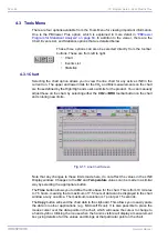
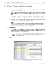
You can send formatted measurement and product data to other computers on your
network, which may have applications that need the data. Do this by selecting the serial
communications port linked to the other computer. You cannot use the same ports that
have already been configured for LINE A and/or LINE B.
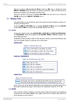
For detailed information on the format of the data elements transmitted, please press the
Help
button on this window and then select
Additional serial output
help.
Check the LINE A and/or LINE B
Output Enable
box to send the
product and measurement data
for that line through this serial
communications port.
Fig 4-10:
Serial Output Screen
Summary of Contents for ORBISPHERE 3624
Page 1: ...Operator Manual ORBISPHERE 3624 Revision F 03 10 2008 ...
Page 2: ......
Page 14: ...8 of 96 Manual Overview 3624 ProBrix Plus Operator Manual ORBISPHERE ...
Page 32: ...26 of 96 Installation 3624 ProBrix Plus Operator Manual ORBISPHERE ...
Page 60: ...54 of 96 PC Program Setup 3624 ProBrix Plus Operator Manual ORBISPHERE ...
Page 68: ...62 of 96 Calibrations 3624 ProBrix Plus Operator Manual ORBISPHERE ...
Page 82: ...76 of 96 Accessories and Attachments 3624 ProBrix Plus Operator Manual ORBISPHERE ...
Page 98: ...92 of 96 Glossary 3624 ProBrix Plus Operator Manual ORBISPHERE ...
Page 101: ...3624 ProBrix Plus User Notes 95 of 96 Operator Manual ORBISPHERE User Notes ...
Page 102: ......


