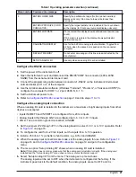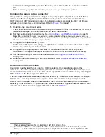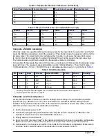
Table 2 Operating parameter selection (continued)
Menu number Command line message
Description
5
ENTER LOWER SIZE
Specify the particle size range (for front panel numerical
display units only). Do not set a lower size to less than
2 microns.
ENTER UPPER SIZE (0 FOR
CUMULATIVE)
Specify the largest particle to be included in the count shown
on the display (for front panel numerical display units only).
6
ENTER FLOW RATE
If 0 is entered, the display shows particles/count period (raw
count).
If 100 mL/min is entered, the display shows particles/mL
(normalized count).
7
CALIBRATING DISPLAY
Use for the 4-20 mA analog output calibration. Toggles from
4-20 mA when the space bar is pushed on the connected
computer.
8
DEFAULT MEMORY
Do not enter a message on this line unless instructed by the
manufacturer.
9
SETUP ANALOG I/O
Use only when an analog I/O card is installed.
Configure the RS232 connection
1.
Set the power of the instrument to off.
2.
Open the instrument cover and disconnect the RS485 "COM" line connector (485A, 485B,
SGND) from the instrument interconnect card.
3.
Connect the programming cable between connector J1-RS232 on the instrument interconnect
card and serial port 1 or 2 of the computer.
4.
Use the terminal emulation software (Windows "Terminal", "Procomm", or "Advanced CRTS") to
configure the computer for COM 1 or 2 port, 9600, N, 8, 1. 5.
5.
Set the instrument power to on.
6.
Refer to
Configure the RS485 connection
on page 19 and do steps
11
to
16
.
Configure the analog input connection
When an analog I/O card is installed in the instrument, a maximum of eight analog inputs from other
devices are accepted.
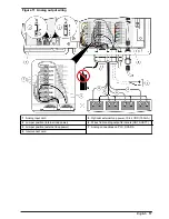
• Inputs IN0/RET0 and IN1/RET1 are configured for 4–20 mA inputs
• Analog inputs AIN2 through AIN7 are configured as 0–5 V or 0–10 V inputs
• AIN 2–7 use a common ground connection, AINGND
1.
Set the jumpers JP2 through JP7 on the analog board to select 0–5 V or 0–10 V operation. Refer
to
Figure 10
on page 16.
2.
To configure the card for 4–20 mA inputs, set the inputs for a 0–5 V operation.
3.
Install a 250 ohm, 1% (or better) shunt resistor, e.g., AIN 2 and AINGND.
4.
When the analog input connections are made, set the analog inputs for use. Refer to
Figure 10
on page 16 and to
Configure the RS485 connection
on page 19 and go to the configuration
menu.
5.
The menu option “Setup Analog I/O” shows when an analog I/O card is installed.
Note: If this option does not show, make sure that the analog card is installed correctly. If the analog card
installed and the "Setup Analog I/O" menu does not show, contact technical support.
6.
Select “Setup Analog I/O” from the menu. The analog set up menu shows.
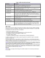
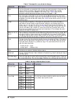
The analog inputs will be set to OFF when the instrument is configured at the factory. If the
instrument goes back to the default condition, the analog inputs are set to OFF and it is
English
21


