background image

15

Section 5

Operation

5.1 Operating the sc controller

The sensor can be operated with all sc controllers. Prior to using the sensor, 
familiarise yourself with the principle of operation of your controller. Learn how to 
navigate in the menus and run appropriate functions.

5.2 Sensor setup

When you connect the sensor for the first time, the serial number of the sensor is 
displayed as the sensor name. You can change the sensor name as follows:

1.

Open the MAIN MENU. 

2.

Choose SENSOR SETUP and accept. 

3.

Choose the related sensor and accept.

4.

Choose CONFIGURE and accept.

5.

Choose EDIT NAME and accept. 

6.

Edit the name and accept to return to the SENSOR SETUP menu.

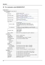
In the same way complete your system configuration using the commands as per 
table 

5.5 "The commands under SENSOR SETUP"

.

5.3 Sensor data logger

A data memory and event memory per sensor are available via the sc controller. 
While measured data are saved in the data memory at stipulated intervals, the 
event memory collects numerous events such as configuration changes, alarms 
and warning conditions. Both the data memory and the event memory can be 
read out in CSV format. For information on how you can download the data, 
please see the controller manual.

5.4 The commands under SENSOR DIAG

SENSOR DIAG

SELECT SENSOR (for several sensors)

ERROR LIST

List of all errors that have occurred (see Section 

7.1 "Error messages"

)

WARNING LIST

List of all warnings that have occurred


(see Sectio

7.2 "Warnings"

)

Summary of Contents for 3798-S sc

Page 1: ...DOC023 52 03252 3798 S sc Digital inductive conductivity sensor User Manual 08 2022 Edition 3...

Page 2: ......

Page 3: ...tallation 12 4 2 1 Installation dimensions 12 Section 5 Operation 15 5 1 Operating the sc controller 15 5 2 Sensor setup 15 5 3 Sensor data logger 15 5 4 The commands under SENSOR DIAG 15 5 5 The comm...

Page 4: ...2 Table of contents...

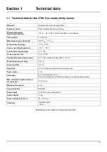
Page 5: ...r operating temperature 20 C 50 C Conductivity response time 2 s T90 Temp response time 2 min T90 Conductivity measuring accuracy 3 of the measured value at 25 C 77 F Temp measuring accuracy 0 2 C Rep...

Page 6: ...4 Technical data...

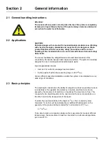
Page 7: ...plications include Inlet and or outlet of a sewage treatment plant Surface water if within the measuring range 250 S cm Various different possible installations enable the system to be adapted to a ve...

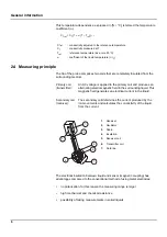
Page 8: ...ssibility of taking measurements in soiled liquids CTref conductivity adjusted to the reference temperature CT conductivity measured at T Tref reference temperature as a rule 25 C coefficient of the l...

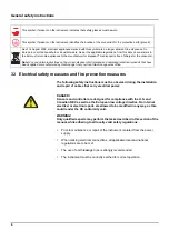
Page 9: ...present on the instrument refers to information in the operating instructions on safe operation and or instructions that provide safety information This symbol if present on a housing or a protective...

Page 10: ...connections all applicable local and national regulations are to be met The use of earth leakage trips is strongly recommended The instrument must be correctly earthed for correct operation This symbo...

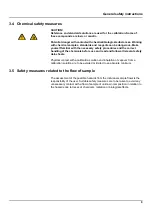
Page 11: ...g of the chemicals before use and read and follow all relevant safety data sheets Physical contact with a calibration solution and inhalation of vapours from a calibration solution are to be avoided o...

Page 12: ...10 General safety instructions...

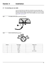
Page 13: ...sor in the future Connecting cables are available in the lengths 5 m 10 m 15 m 20 m 30 m and 50 m From a length of 100 m a bus termination box must be integrated see Section 8 Spare parts Fig 1 Connec...

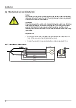
Page 14: ...with chemical samples standards and reagents can be dangerous Make yourself familiar with the necessary safety procedures and the correct handling of the chemicals before use and read and follow all...

Page 15: ...Installation 13 Fig 3 Installation examples 1 Rim mounting chain bracket PVC or stainless steel 2 Rim mounting immersed tube PVC or stainless steel...

Page 16: ...14 Installation...

Page 17: ...return to the SENSOR SETUP menu In the same way complete your system configuration using the commands as per table 5 5 The commands under SENSOR SETUP 5 3 Sensor data logger A data memory and event m...

Page 18: ...n is due CORR FACTORS Choose between TEMP OFFSET GAIN CORR and GAIN VALUE SET CAL DEFLT Return to the factory settings after prompt for confirmation CONFIGURE EDIT NAME Enter a 10 character name PARAM...

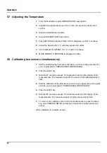
Page 19: ...LETE 5 Confirm that you have replaced the sensor in the sample flow and accept 5 6 2 Calibration in air ELECTRIC SPAN 1 Remove the probe from the flow of sample clean and dry 2 Connect a defined resis...

Page 20: ...nd when you arrive at the point at which you are prompted to PRESS ENTER WHEN STABLE 2 Press the BACK key 3 Select EXIT and press accept The instrument returns to the display of the measurements The m...

Page 21: ...s You can set the calibration interval in the sensor setup The controller then reminds you when calibration is due 6 2 Cleaning the sensor Clean the sensor with a jet of water If there is still soilin...

Page 22: ...20 Maintenance...

Page 23: ...k the cable to the controller TEMP TOO LOW Measured temperature 5 C Ensure that the medium temperature is 5 C TEMP TOO HIGH Measured temperature 100 C Ensure that the medium temperature is 100 C COND...

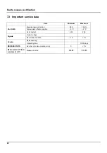
Page 24: ...trical gain correction 95 105 Temperature offset correction 5 C 5 C Cell constant 2 50 2 00 Signals Output voltage Raw measured data 1 1 Counter Desiccant bag Operating time 1000 days MODBUS STATS Num...

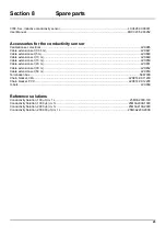
Page 25: ...10 m LZX849 Cable extension set 15 m LZX850 Cable extension set 20 m LZX851 Cable extension set 30 m LZX852 Cable extension set 50 m LZX853 Termination box 5867000 Chain bracket V4A LZX914 99 11200 C...

Page 26: ...24 Spare parts...

Page 27: ...t 7 days after the identification of the fault If the customer fails to notify the supplier the product is considered approved despite the defect Further liability for any direct or indirect damages i...

Page 28: ...26 Warranty and liability...

Page 29: ...1 R W sensorname 0 Sensorname 1 40029 Integer 1 R W sensorname 1 Sensorname 2 40030 Integer 1 R W sensorname 2 Sensorname 3 40031 Integer 1 R W sensorname 3 Sensorname 4 40032 Integer 1 R W sensornam...

Page 30: ...R W RS_tgTempOffsetCorr 40084 Integer 1 R W RS_tgTempRef 40085 Integer 1 R W RS_tgTempManual 40086 Integer 1 R W Analogue Output Command Serial Number String 0 40087 Integer 1 R W RS_sn_string 0 Seri...

Page 31: ......

Page 32: ...ach com HACH LANGE GMBH Willst tterstra e 11 D 40549 D sseldorf Germany Tel 49 0 2 11 52 88 320 Fax 49 0 2 11 52 88 210 info de hach com www de hach com HACH LANGE S rl 6 route de Compois 1222 V senaz...

Reviews: