1.
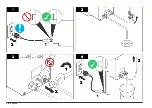
Connect the local BNC cables for the analyzers and any non-
integrated controllers(s) to the middle coupling of a supplied BNC tee
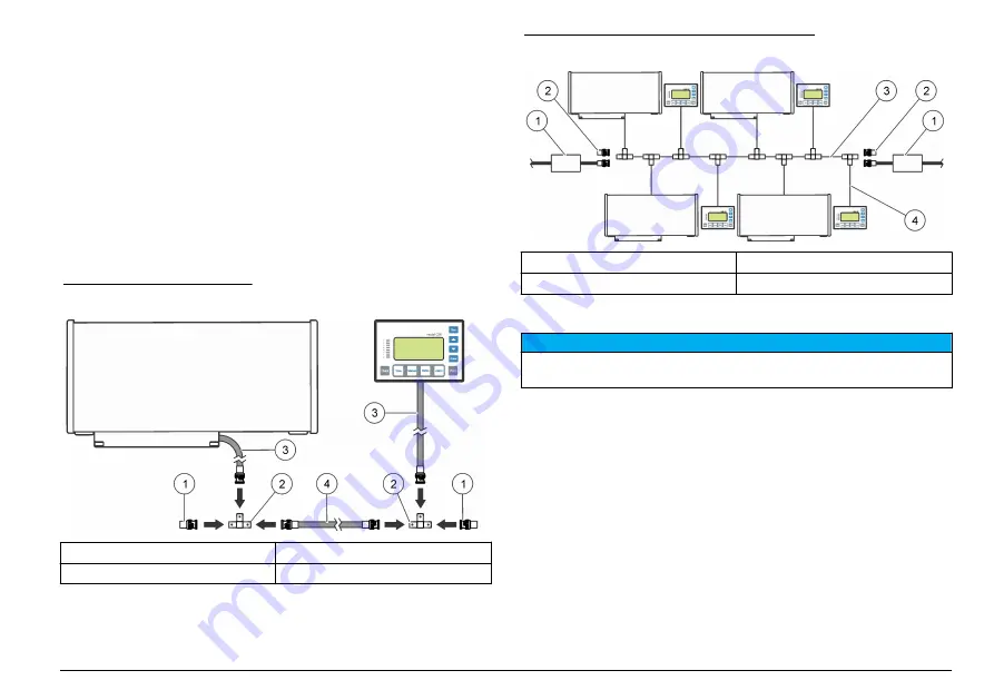
connector. Refer to
. Gently push the cable onto the
coupling. Twist the cable onto the connector until it locks on the
coupling.
2.
Connect the BNC tee connectors with sections of twin-axial trunk
cable. Refer to
. A 3.3 m (10 ft) trunk cable is supplied. Use
a 120-ohm, AWG 24, shielded twisted pair cable made for EIA
RS485 applications for the trunk cable.
3.
If the trunk line is 167 m (500 ft) in length or less, connect a supplied
passive terminator to the open coupling of the BNC tee connectors at
both ends of the trunk cable. Termination is necessary for reliable
communications.
4.
If the trunk line is more than 167 m (500 ft) in length, refer to
Figure 15 Cable connections
1
Passive terminator
3
Local BNC cable
2
BNC tee connector
4
Trunk cable
Figure 16 A-Net communication connections
1
AC-powered terminator
3
Trunk cable
2
Passive terminator
4
Local BNC cable
Use active termination
N O T I C E
Do not use standard BNC terminators. Only use passive or active terminators
supplied by the manufacturer.
The A-Net network must be configured as one trunk cable with local
BNC cables no longer than 1 m (3 ft) in length. The trunk cable can be a
maximum of 1000 m (3000 ft), not including local BNC cable lengths.
When the trunk cable length will be more than 167 m (500 ft):
• Install the trunk cable in conduit that does not contain any other
cables or AC buses to prevent potential electrical interference.
• Use active (AC-powered) termination to control noise and supply a
clean communication signal.
Active termination:
English
17
Summary of Contents for A1000
Page 2: ...English 3 Deutsch 29 Italiano 57 Fran ais 83 Espa ol 110 2...
Page 28: ...28 English...
Page 56: ...56 Deutsch...
Page 82: ...82 Italiano...
Page 109: ...Fran ais 109...
Page 136: ...136 Espa ol...
Page 137: ......


