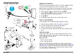
1.
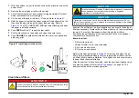
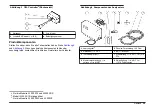
With the analyzer on, pull the black knob on the printer and open the
printer cover.
2.
Remove the empty paper roll from the printer.
3.
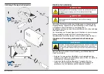
Cut off the first section of a new paper roll (approximately 8 inches)
which is attached to the roll with glue.
4.
Cut the end of the paper roll into a "V" shape. Refer to
5.
Hold the paper roll so that the paper comes off the bottom of the roll,
then slide the paper through the paper feed opening. Refer to
. The OFF LINE/PAPER END light stops flashing and when
the paper is installed correctly.
6.
Push
FEED
until the “V” is past the tear shield.
7.
Pull the black knob on the printer and close the printer cover.
8.
Push
ONLINE
. Any data accumulated at the printer is supplied as a
hard copy print.
Figure 21 Install paper in the printer
Clean the air filters
D A N G E R
Electrocution hazard. Remove all power from the instrument and relay
connections before this maintenance task is started.
N O T I C E
Potential Instrument Damage. Delicate internal electronic components
can be damaged by static electricity, resulting in degraded
performance or eventual failure.
N O T I C E
Tighten the compression nut 1/8 turn to make a plumbing connection. Do not
tighten the compression nut more because this can cause damage to the fittings
or ferrules and cause leaks.
Examine the air filters for air flow restriction once a month. Clean the air
filters as necessary. Replace the air filters when the UV lamp is replaced
(every 6–12 months). Decreased air flow through the air filters
decreases the performance of the analyzer and causes the analyzer
components to become too hot.
Items to collect:
• 5/64-in. allen wrench
• Phillips screwdriver (to remove handle)
• 3/4-in. open-end wrench
• 9/16-in. open-end wrench
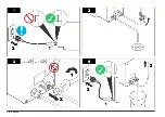
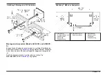
Refer to the illustrated steps in
to remove and clean the air
filters. Do the illustrated steps in reverse to install the air filters. Let the
air filters fully dry before installation. Fully tighten the end cover screws
to keep the environmental rating.
After the analyzer is fully assembled, open the upstream isolation valve
and start the analyzer. Refer to
on page 22. The
analyzer continues the previous operation.
English
25
Summary of Contents for A1000
Page 2: ...English 3 Deutsch 29 Italiano 57 Fran ais 83 Espa ol 110 2...
Page 28: ...28 English...
Page 56: ...56 Deutsch...
Page 82: ...82 Italiano...
Page 109: ...Fran ais 109...
Page 136: ...136 Espa ol...
Page 137: ......


