59
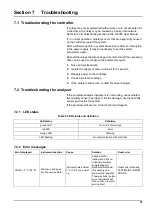
Troubleshooting
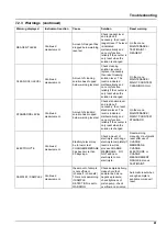
CUV TOO HOT
Service state, cuvette
heating off!
The cuvette/sample is
over-heated.
Check if incoming
sample is in the
specified range and
increase the cuvette
temperature setpoint
(CONFIGURE>
CUVETTE TEMP.)
Use lowest possible
cuvette temperature.
Call service if error
continue
Reset error manually
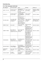
ELECTRODE SLOPE
Service state
The error occurs if the
electrode slope is not
in the range of -50mV
to -70mV
Change membrane
and electrolyte, if there
is still a problem, check
standards,
measurement range
and chemistry, check
flow rate. If all OK, but
error still present, fit
new electrode
Reset error manually
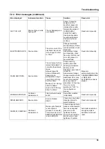
FALSE ELEC DATA
Service state
The mV value for Zero
related to Standard 1 is
not within the allowed
range.
Allowed range for
(Uzero-UStandard1)
depending on
measurement range:
Low (0.05 to 20 mg):
5mV to 200mV
Medium (1 to 100 mg):
20mV to 265mV
High (10 to 1000 mg):
50mV to 315mV
Check cleaning
solution (level and
delivery) and sample
delivery, check
Standard 1 (level and if
correct for
measurement range),
change membrane and
elektrolyte. Error may
occure when sample
has very unusual
properties. In this case
the error can be
switched to "OFF" in
the configuration
menue.
Manual or
automatically when the
CHANGE MEMBRANE
or REPLACE
ELCTRODE pocess is
started
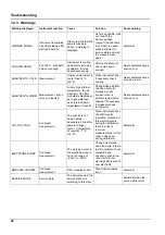
MODULES CONTAM.
Continued
measurement
Filter modules heavily
soiled
Clean filter modules
immediately
Reset error manually
DRAIN BLOCKED
Service state
Drain is blocked
(lime?)
Check drain line. Adapt
cleaning interval to
water hardness.
Reset error manually
SAMPLE1 / SAMPLE2
Continued
measurement
the amount of sample
is not sufficient
(channel1 / channel2)
This occurs as error if
SAMPLE DETECTION
is set to ERROR
Check sample delivery,
make sure that sample
line has no negative
pressure, check
tightness of piston
pump, check overflow
and air valve, check
tightness of system.
Automatic reset when
enough sample is
available or manuell
reset
7.2.2 Error messages (continued)
Error displayed
Instrument reaction
Cause
Solution
Reset error
Summary of Contents for AMTAX sc
Page 2: ......
Page 7: ...7 Specifications Figure 1 Instrument dimensions AMTAX sc...
Page 12: ...12 General Information...
Page 36: ...36 System Start Up...
Page 44: ...44 Operation...
Page 56: ...56 Maintenance...
Page 64: ...64 Troubleshooting...
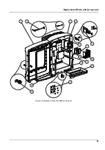
Page 69: ...69 Replacement Parts and Accessorie Figure 23 Analyzer enclosure AMTAX indoor sc...
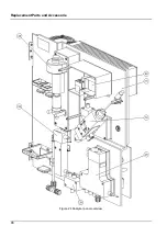
Page 70: ...70 Replacement Parts and Accessorie Figure 24 Analyzer panel overview...
Page 71: ...71 Replacement Parts and Accessorie Figure 25 Analyzer panel front view details...
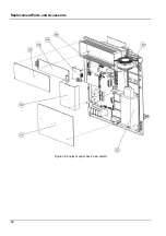
Page 72: ...72 Replacement Parts and Accessorie Figure 26 Analyzer panel back view details...
Page 76: ...76 Warranty and liability...


