60
Troubleshooting
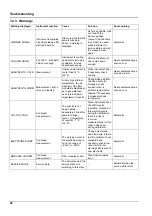
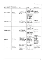
7.2.3 Warnings
Warning displayed
Instrument reaction
Cause
Solution
Reset warning
WARMUP PHASE
Instrument is warming
up sample tubing after
start (de-frosting)
If there is a risk that the
sample tubes are
frozen, a warning is
displayed
As far as possible, wait
until end of the
warm-up phase
(except if certain there
is no frost), to cancel
place instrument in
service state and start
the measurement
again
Automatic
COOLING DOWN
Fan 100 % , standstill
until cool enough
Instrument is cooling
down after start using
ventilation, if it was
heated excessively
Wait until instrument
has cooled down
enough
Reset, automatically as
soon as cool
ANALYZER TO COLD
Measurement
Interior of instrument is
cooler than 15 °C
(59 °F)
Close instrument door,
if necessary check
heating
Reset, automatically as
soon as warmer
ANALYZER TO WARM
Measurement, but no
more air cleaning
At very high internal
temperature, the air
cleaning of the filter
modules is disabled so
as to generate less
heat. internal temp =
target temp of cuvette
Change/clean air filter,
check air ducts for
blockage, check
enclosure fan, is
ambient temperature
allowed? If necessary
increase electrode
temperature
Reset, automatically as
soon as cool
CUV TOO COOL
Continued
measurement
The cuvette is not
being heated
adequately 2 min after
sample change:
temp. = ((target temp.
of cuvette) –1 °C
(34 °F))
Close instrument door,
check/fit cuvette
insulation. Attention: If
this warning occurs
during the calibration,
there is a risk of
incorrect
measurements, for this
reason close door
during calibration!
Automatic
ELECTRODE SLOPE
Continued
measurement
The warning occurs if
the electrode slope is
not in the range of
–55mV to –67mV
Change membrane
and electrolyte, if there
is still a problem, check
standards and
chemistry, check flow
rate. If all OK, but
warning still present, fit
new electrode
Automatic
MODULES CONTAM.
Continued
measurement
Filter modules soiled
Clean filter modules
soon
Automatic
SERVICE MODE
Service state
The instrument is in the
service state or is
switching to this state
–
Automatic when the
service state is left
Summary of Contents for AMTAX sc
Page 2: ......
Page 7: ...7 Specifications Figure 1 Instrument dimensions AMTAX sc...
Page 12: ...12 General Information...
Page 36: ...36 System Start Up...
Page 44: ...44 Operation...
Page 56: ...56 Maintenance...
Page 64: ...64 Troubleshooting...
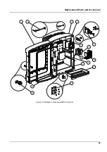
Page 69: ...69 Replacement Parts and Accessorie Figure 23 Analyzer enclosure AMTAX indoor sc...
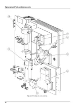
Page 70: ...70 Replacement Parts and Accessorie Figure 24 Analyzer panel overview...
Page 71: ...71 Replacement Parts and Accessorie Figure 25 Analyzer panel front view details...
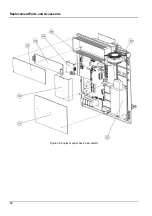
Page 72: ...72 Replacement Parts and Accessorie Figure 26 Analyzer panel back view details...
Page 76: ...76 Warranty and liability...


