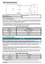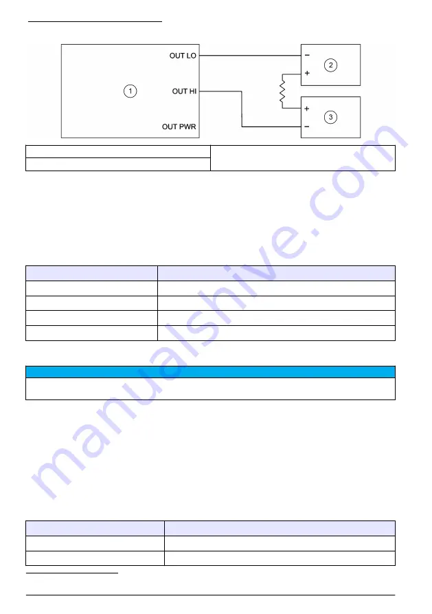
Figure 7 Externally-powered loop
1
Analog output
3
External device
2
External power supply
Connect the digital inputs
The I/O module has four digital inputs
3
. Connect a remote device and/or a switch to the digital inputs.
Refer to
to connect the digital inputs. Refer to
on page 3 for the digital input specifications.
Each digital input has a positive terminal and a shared common with an input resistance of 120 kΩ.
The default threshold is 1.5 V. When the optional customer supplied threshold is used, the threshold
is set at 50% of the voltage applied to the threshold pin (0 to 25 VDC).
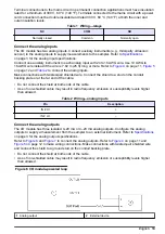
Table 3 Wiring—digital inputs
Pin
Description
COM (pin 1)
Negative for THRESHOLD
THRESHOLD
25 VDC maximum
COM
Negative
IN #
Positive
Connect the digital outputs
N O T I C E
Do not use the digital outputs for process control functions such as pump on/off switching or water system
shutdown. The digital output connections do not replace a PLC (programmable logic controller).
The I/O module has four digital outputs. Connect a compatible device such as a remote alarm
indicator, buzzer or PLC to the digital outputs. Refer to
on page 11,
on page 12 and
to connect the digital outputs. Refer to
on page 3 for the digital output
specifications.
The digital outputs are independent floating switches when the PULLUP V input and associated
internal pull-up resistors are not used. The switches are normally open. The switches close when the
user-selected alarm conditions occur.
To use the optional PULLUP V input and the related internal 10 kΩ internal pull-up resistors, supply
the applicable voltage to the PULLUP V and COM (pin 14) pins. Then, connect a jumper from the
OUT # LO pin to the COM pin. The output signal logic is active low.
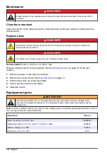
Table 4 Wiring—digital outputs
Pin
Description
OUT # HI
Positive
OUT # LO
Negative
3
The digital inputs are not supported by the AS950 controller firmware at the initial release.
14
English
Summary of Contents for IO9000
Page 2: ...English 3 Français 19 Español 37 Português 54 中文 72 日本語 88 2 ...
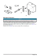
Page 7: ...Figure 2 Wall mounting English 7 ...
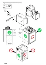
Page 8: ...Figure 3 Mounting locations on the sampler 8 English ...
Page 24: ...Figure 2 Montage sur un mur 24 Français ...
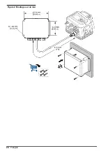
Page 25: ...Figure 3 Emplacements de montage sur l échantillonneur Français 25 ...
Page 42: ...Figura 3 Ubicaciones de montaje en el tomamuestras 42 Español ...
Page 59: ...Figura 2 Montagem na parede Português 59 ...
Page 60: ...Figura 3 Locais de montagem no amostrador 60 Português ...
Page 76: ...图 2 墙面安装 76 中文 ...
Page 77: ...图 3 采样仪上的安装位置 中文 77 ...
Page 79: ...拆下护盖 按照如下图示步骤拆下护盖 布线概述 图 4 显示了布线连接以及保险丝位置 请参阅 图 5 准备和安装电线 中文 79 ...
Page 93: ...図 3 サンプラーの取り付け場所 日本語 93 ...
Page 105: ......


